PAGE 1
PAGE 2
(FOR MORE RECENT DEVELOPMENTS SEE
HERE)
DIY CONTROL LOADER COLUMN PROJECT
(Video Clips on
Page 2)
In the DIY force
feedback yoke pages I described an ongoing project to
build DIY force feedback flight sim controls. Although the overall
system seemed to work reasonably well one big issue was with
the smoothness of the force feel, and this
was due to the cogging or commutation ripple in shaft
torque produced by the electric motors used to power the
controls. I felt that the ripple spoiled the feel of the
force feedback.
I've now been able to try good quality disc armature motors1
in the system to take the project a step further. With these motors I think the quality of the
loading on the controls is greatly improved over the skewed
rotor servo motors I tried last time; generally the forces are
smoother and the motors offer little motion resistance when
operating at light force levels. The force feedback isn't
perfect however as some commutation disturbance in the motor
torque output is still discernable especially at higher force levels -
how significant individual users might think this is is an
interesting question! If I'm honest with myself I think it is noticeable.
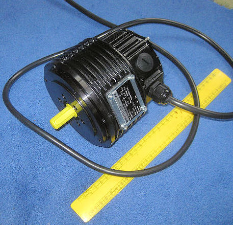
The motors I've used are Mavilor MSS-4 DC servo motors
(below left). They are quite large and this has
prevented their use in the flight yoke setup so I've built a
simple flight column test rig to further work on the system.
The smaller MSS-2 motor in the same range might be a more
suitable choice for a yoke build - however not being sure of the
levels of torque performance needed I went for these bigger
motors for testing.
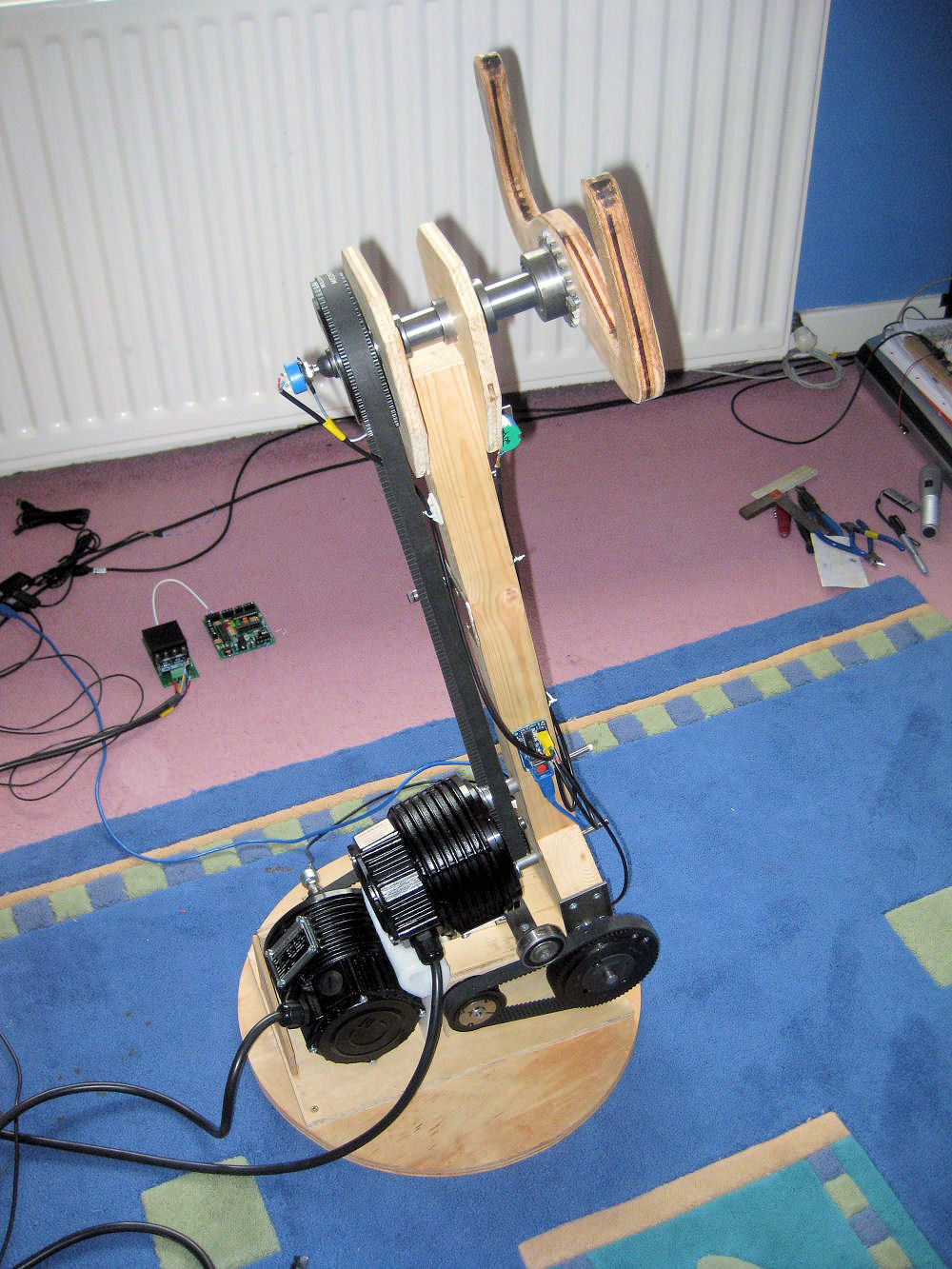
THE TEST FLIGHT COLUMN
The control loader flight column test rig is shown in the
image above right. You can see I've not spent much time
trying to make it look pretty - however it does function.
There are several features of the design that have turned
out to be important
in getting the force feedback system working and these are -
-
Rigid structural elements to minimise flexure of the
drive mechanism under load.
-
Low friction, well fitting pivots for both elevator and
aileron axis movements. The aileron axis is needle
roller bearing mounted, the column is pivoted at the
base on a steel pin mounted in close fitting steel
housings. I think ball bearings might further improve
things.
-
Toothed belt transmissions connecting the servo motors
to the column and yoke with belt tension adjustment to
ensure there is no backlash (slack) in the transmission.
-
Transmission shafts bearing mounted in rigid housings to
minimise friction and ensure constraint of any belt
pulley displacements which might lead to slackened
belts.
-
Precision position feedback potentiometers geared
without backlash to the movement axes. (The pots are
geared to utilise as much of their full electrical
travel as possible and are used with a 12bit joystick
card to generate the necessary resolution of position
feedback.)
|
Disc
armature DC servo motor |
It looks like all the above mechanical elements of the design are
necessary for acceptable performance of the force feedback
system. Any kind of lag, deadband, backlash or softness
anywhere between the accurate reporting of column movement
to the PC and the application of the force response from the
motors to the column will compromise the performance of the
system.
The need for this mechanical design/build performance is
matched by the need for similar levels of performance from
the electrical/control system and the force feedback
software. It is helpful to think of the
whole system as a chain of elements that needs to be
designed to minimse the time taken and maximise the accuracy
with which the column movement is detected and the force
response to this movement is applied to the column.
For information the elevator movement range of the test
flight column is roughly 300mm and the aileron axis rotation
is just short of +/- 90 Deg. The aileron drive has a 4:1
speed reduction between the MSS-4 motor and the yoke axis,
and the elevator drive has a 16:1 reduction made in two 4:1
stages. The elevator drive motor works harder than the
aileron drive and I think it might be possible to use a
smaller MSS-2 motor for the latter which would ease the
mechanical layout problems.
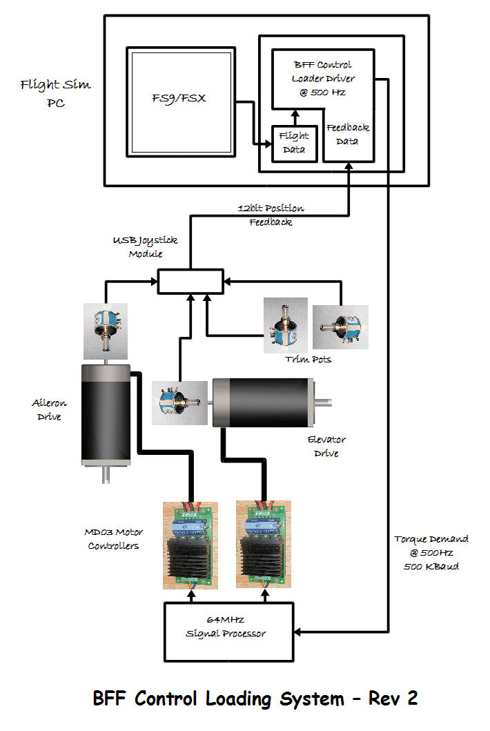
CONTROL SYSTEM & SOFTWARE
|
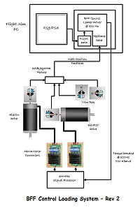
Improved
DIY force feedback system |
I've managed to improve both the electrical and control
system and the PC force feedback software. In particular
following my own experiments with the system and also
suggestions made by several emailers (thanks to all the
helpful suggestions emailed in) I've worked to increase the
refresh rate of the main force feedback to loop to 500 Hz.
Speeds higher than this are used in many commercial control
loader systems however an aim of the project was to try and
get reasonable levels of performance using low cost components.
This has not been possible regarding the motors because of
their critical role in the system, however I have
managed to keep the cost of the rest of the system down.
The force feedback software now does its load calculations
at a target 500 Hz. This is the limit of the 12 bit joystick
card (Leo Bodnar's) used to report control axis positions.
Note the feedback pots on the flight column are the same
ones FSX uses, but they need to be precision pots geared to
utilise their full electrical travel. Flight data from FSX/9 providing airspeed,
engine thrust, acceleration data etc is brought into the
calculations at the frame rate of the flight sim. The
calculated force demands are exported by the software using
500K baud serial comms and are processed by a new signal
processor unit based on the PICAXE 20X2 micro controller
running at 64 MHZ. The 500K baud comms is supported by the
standard FTDI chip based picaxe USB download cable (with
some serial port setting adjustments), and 64 MHz is a
standard speed for the 20X2 chip. The result is that the
voltage demands to the MD03 motor controllers on the I2C
data bus are refreshed at a target 500Hz.
The MD03 motor controllers use 8 bit resolution in their
motor voltage outputs, with their separate direction control
this gives torque demand over a range of nominally +/-255
steps.
This could be an issue if the system was set up to produce a
maximum force output that was much higher than the usual
working forces experienced during normal flight conditions.
So the 8 bit resolution does pose a limitation. I have the
test rig set up to try and match the maximum 255 demand
output to what I think are the max feedback forces
associated with flying at the normal airspeed limit of the
aircraft. This ensures that flight in the normal speed
ranges produces forces that use a good proportion of the
available 8 bit resolution and do not feel rough because of
the minimum step change in motor torque that can be
achieved. This is done by selecting the right voltage supply
for the MD03. The clear implication though is that trying to
set up a force range that includes very high failure mode
forces for example would probably make the feel at more
normal lower forces rougher.
The actual refresh speeds achieved by the system will be PC dependent. On my oldish
dual core AMD Athlon 64 6000+ machine I get slower refresh
speeds when running with FSX on the same PC when the force
feedback software is set not to hog CPU (I get about 350 Hz). I
have also written a LAN version of the software and using
this to run the force feedback system on an old single core
machine I get the full 500Hz as there is no FSX to compete
with. I suspect that a newer 4 or higher core machine might
be quite happy running both FSX and the force feedback
software - something to test.
|
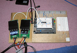
Motor
drive test set up with 64MHz signal processor unit
on breadboard |
The higher refresh speeds are required because they are important for some of the
components of the force feedback, but not all. The main
benefit is to reduce system lag when processing the
main control surface deflection related aerodynamic force
component. At lower refresh rates a greater delay is present
in how quickly the force responds to stick movement. If the
stick is moved fast enough the forcing can get sufficiently
out of phase with the motion to start to induce unstable
oscillations - this is not good! At the higher
refresh rates this does not happen and the stick response is
stable even if it is accidentally let go when in flight. See
- the video clips on
the next page.
Secondary, but still potentially important effects of the
higher refresh rates are to improve the effectiveness with
which speed of motion related damping can be added to the
stick response, and also how friction (or -ve friction) can
be simulated. I am finding that there are limits here
however, and although this low cost system seems to be able
to add moderate damping and friction effects the force feel
deteriorates if I overdo it and try to very heavily damp the
column movement through the dynamic model. One problem is that small commutation based
torque ripples from the motor result in small speed
fluctuations in the column motion which are then magnified
by a high speed related damping force gain in the closed loop. The frequency of these fluctuations is much higher
than the stick movements used for flight control and would
probably need a significant further uplift in the force
feedback loop refresh speed to remove the small system lag
causing the magnification. An alternative would be not to
use DC commutated motors - but both solutions would take us
further towards commercial control loader system specs and
the price tags associated with them.
So I think the system performs well for the price, but it
looks like there is a
firm limit to the capabilities of such low cost
electrical/control components.
Continued on page
2...... Performance and Video Clips
1. Many thanks are due to Don McKellow who
has kindly lent me the Mavilor disc armature motors to work
with. They are destined for Dons' full size B777 sim once
I've made enough progress on the system (assuming I don't
break them first). Don is a B777 training captain.
© This site is
copyrighted, If you'd like more information or have any
comments please contact me at