|
BFF FFB Steering Wheel |
Here's a bit of fun!
I've wondered for a while whether or not the brushless motor
driver cards used in the flight control loading systems
might be used for a steering wheel force feedback system. So
I thought I'd have a shot at developing one....
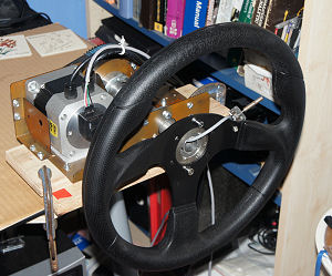
The experimental FFB wheel is shown right. Mechanically the
steering wheel drive is similar to the aileron axis on
flight controls. But mathematically the loading calculations
are quite a bit different - and the way the calculations are
distributed over the PC and motor driver card is also quite
a bit different as a result.
A
significant difference is the higher rate at which the
forces change, and I changed the system design to reflect
this. It might be important to say here that I haven't used
the standard FFB output from the racing sim - instead I've
extracted dynamic data directly from the sim and used this
to calculate the slip angles and forces etc required for the
FFB system. This has let me play with the force calulations....
|

BFF FFB Steering Wheel |
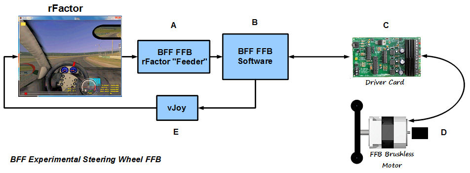
The experimental system is configured as shown in the
diagram - here are the main elements:
-
rFactor - I used this sim to experiment with because of
the fairly good data set available via its internals
plugin.
-
A - A "feeder" application which stands between
the racing sim and the main FFB software (B). The feeder
app pulls the live dynamics data from the sim, does a
bit of processing and sends it to the FFB software. The
data is updated each sim frame and principally consists
of a steering restoring moment (Mz) .v. tyre slip angle
curve and vehicle slip angle data.
-
B - The main BFF FFB application which takes the
live Mz .v. slip curve data and vehicle slip data and
exports it to the brushless motor driver card.
Additional force data such for friction, damping and
vibrations are also sent to the card.
The FFB app also receives back from the card steering
wheel position data which it passes back to the sim in
the form of virtual joystick position movements (E).
-
C - The motor driver card uses the vehicle slip
angle data together with the wheel position to calculate
the instantaneous tyre slip angle. It then uses this to
calculate the instantaneous restoring moment using the
latest Mz .v. Slip curve data received from the PC.
-
D - Brushless motor to produce the wheel feedback
torque - I used a single stage belt reduction to bring
up the torque to a working level. The motor is the same
one as I use in the flight control loading systems and
gives smooth torque output.
-
E - vJoy virtual joystick used to send the wheel
position data back to the sim so that a separate
joystick card isn't needed.
The experimental system configuration allows the data comms
between the software and cards to take place at
approximately the frame rate of the sim. Whereas the actual
force calculations onboard the card are carried out much
faster to keep the drive system dynamically stable.
|

Live scoping of force
data... |
By using a separate feeder application I can also write and
run different restoring moment .v. slip angle tyre models
without affecting the main FFB app or the card programming.
For example the tyre model used in the video clips below is
a Pacejka "Magic Formula" model with additional processing
to handle low speed changes in the steering force response.
I thought in the future I might be able to make the feeder
app code open source to allow users to experiment with the
models and/or write their own to suit specific cars and tyre
responses etc.. This is quite challenging, but might suit
keener racers who would like to manipulate the forces at a
fairly deep level.
The Pacejka Mz curve calcs in the test feeder app use live
vehicle wheel downloading data which is pulled from the sim
at the sim frame rate - effectively a new Mz .v. slip curve
is calculated and exported to the driver card each frame. It
changes continually with the continual changes in wheel
loading reported by the sim (including impact, pot hole and
off-road loading changes). Tyre model settings such as the
Pacejka tyre coefficients, camber angles etc are defined
within the feeder app coding. Ideally the user would match
these to those used in the sim's tyre setup.
NOTE the feeder app could be written with other tyre
restoring moment models - it doesn't need to be Pacejka.
MOVIE CLIPS
Here are a couple of quick movie clips to illustrate the
system.
This first one just gives a few views of the steering wheel
mechanical assembly -
http://youtu.be/H5U3qlRC4yY
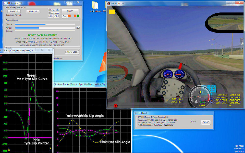
The second clip below is a longer one showing the system in
action. I've tried to show the on-screen data together with
the steering wheel movements. Unfortunately you can't feel
the forces but you can watch the oscilloscope data which
shows how the parameters change with the car dynamic
situation.
http://youtu.be/ZwsFQrLhkL0
Watch the left-most scope screen - you'll probably recognise
the shape of the live Mz .v. Slip curve (green trace) - note
how it changes as the wheel loading changes. For example
braking increases the front wheel download and raises
steering torque levels, whereas accelerating has the
opposite effect and lightens the steering forces. The pink
"pointer" trace on the same scope shows the instantaneous
tyre slip angle - so you can see where on the Mz .v. slip
curve the steering is operating.
In the right-hand scope the pink trace is also tyre slip
angle. The yellow trace is vehicle slip angle - watch how
these change as the vehicle corners - when the vehicle
starts to let go on a corner you'll see the vehicle slip
angle increase and the tyre slip with it....
The green trace on the right-hand scope is the motor torque
output.
OVERALL
Overall the FFB wheel seems to work quite well - the torque
response to tyre slip is there and the loading responds to
live wheel loading changes reported by the sim. The force
response is sharp. Additional effects such as friction and
damping can be added-in as can vibrations based on engine
speed and power etc.
The system configuration with the feeder app allows a lot of
flexibility in the tyre response modelling, but this would
probably be of interest mainly to enthusiasts given the
knowledge levels required.
For the overall system approach to work all the automatic
steering help and speed adjustments that the sim can apply
need to be disabled so that the steering angles used by the
FFB system properly match those used by the sim. This
probably adds "realism" to the experience right enough
- it might explain why my driving is so bad (any excuse)!
There might be enough potential in the system to work on it
a bit more - I'll post any updates when I have them.
© This site is
copyrighted, If you'd like more information or have any
comments please contact me at