|

3-DOF
Motion Cockpit - initial design. |
JAN '08 I've had a number of enquiries about detailed
mechanical plans for the motion cockpit, or for details of
the construction. I don't intend to draft a full set of
detailed plans as I think the design is probably a bit too
complicated for many DIY'ers (not all) and the returns won't
justify the outlay in time to prepare the plans.
However
to provide some help for other DIY'ers I've tidied up my 3D
CAD model of the design and made one or two changes to
reflect mods made during and after the build and have
produced a series of high resolution images which should
show, at least, the principals of the construction.
Not all fasteners have been included in the images.
I've added one or two comments where they might be
helpful - but this page is really just about the images.
Note you can't get accurate dimensional information from the
images - for that type of detail you would need the 3D CAD
model and the CAD software to read it.
NOTE - some of the
images are quite large and may take a moment to download.
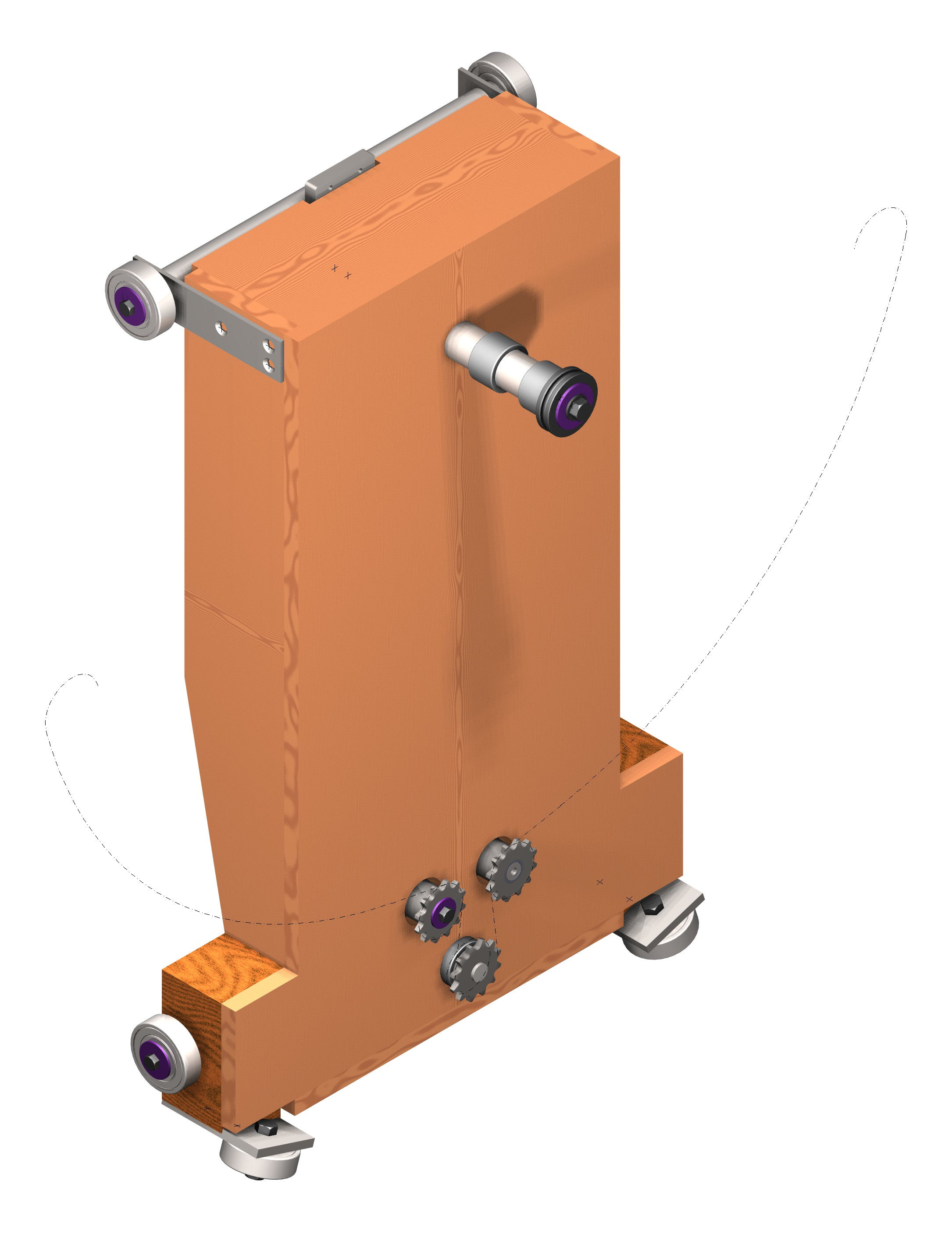
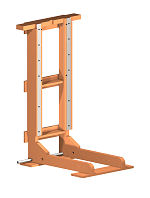
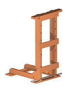
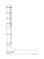
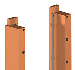
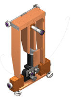
Motion Cockpit Wall Brace
Timber structure but with steel flats for roller running surfaces
- the rollers are heavily loaded.
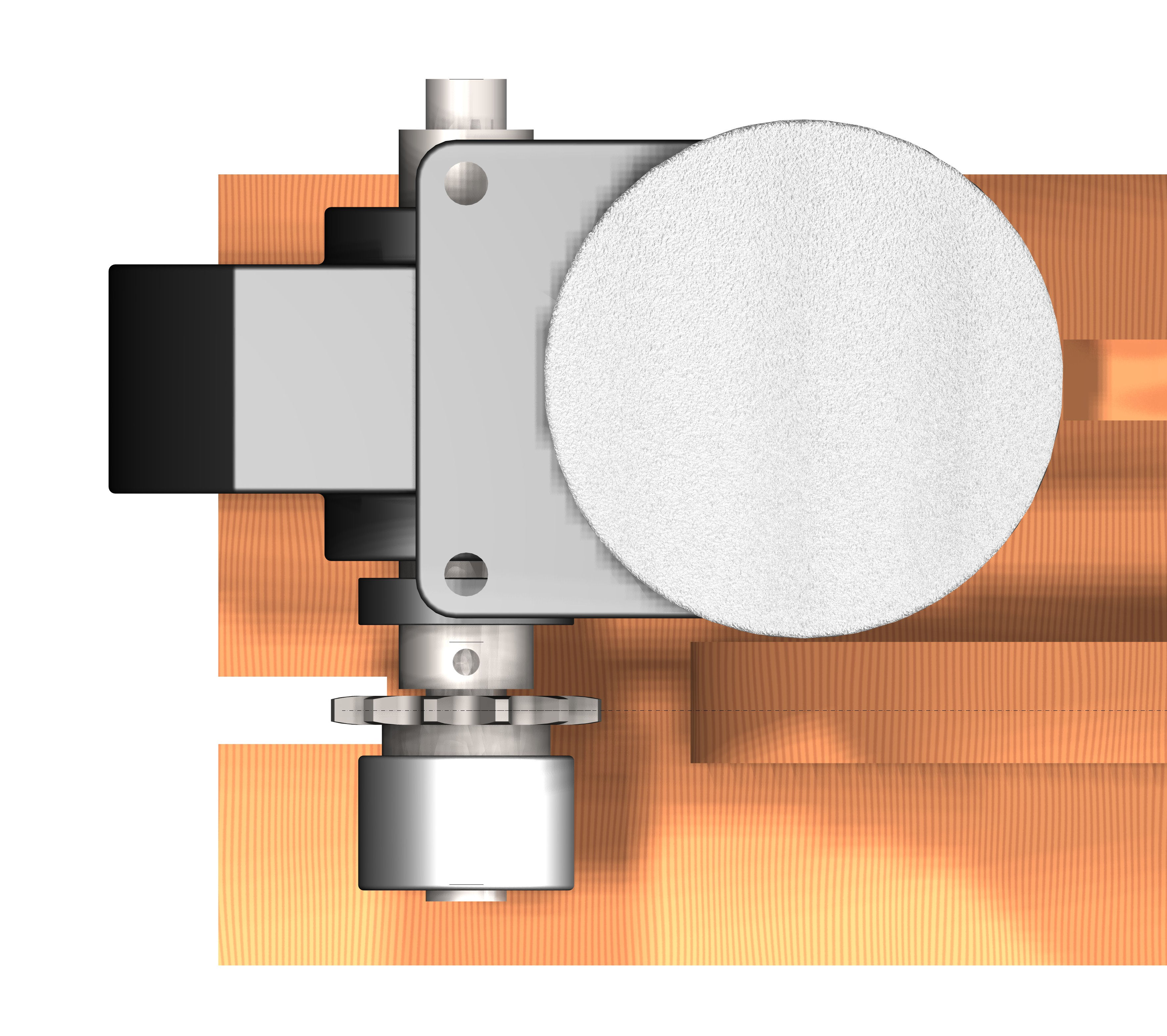
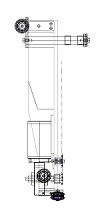
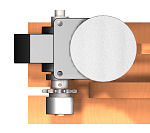
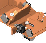
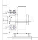
Heave Carriage
Timber with steel stress components. The motor drives a 3/8"
roller chain to pitch the cockpit cradle (see below). Needle
roller bearings and thrust ball bearings on the main cradle
support pin. The lower-most rollers should be soft-tyred (eg
roller blade wheels) for quiet rolling on the cradle. I
eventually fitted a small vibration isolation connection where
the support chain is attached to remove slight but noticeable
chain vibration from the cockpit.


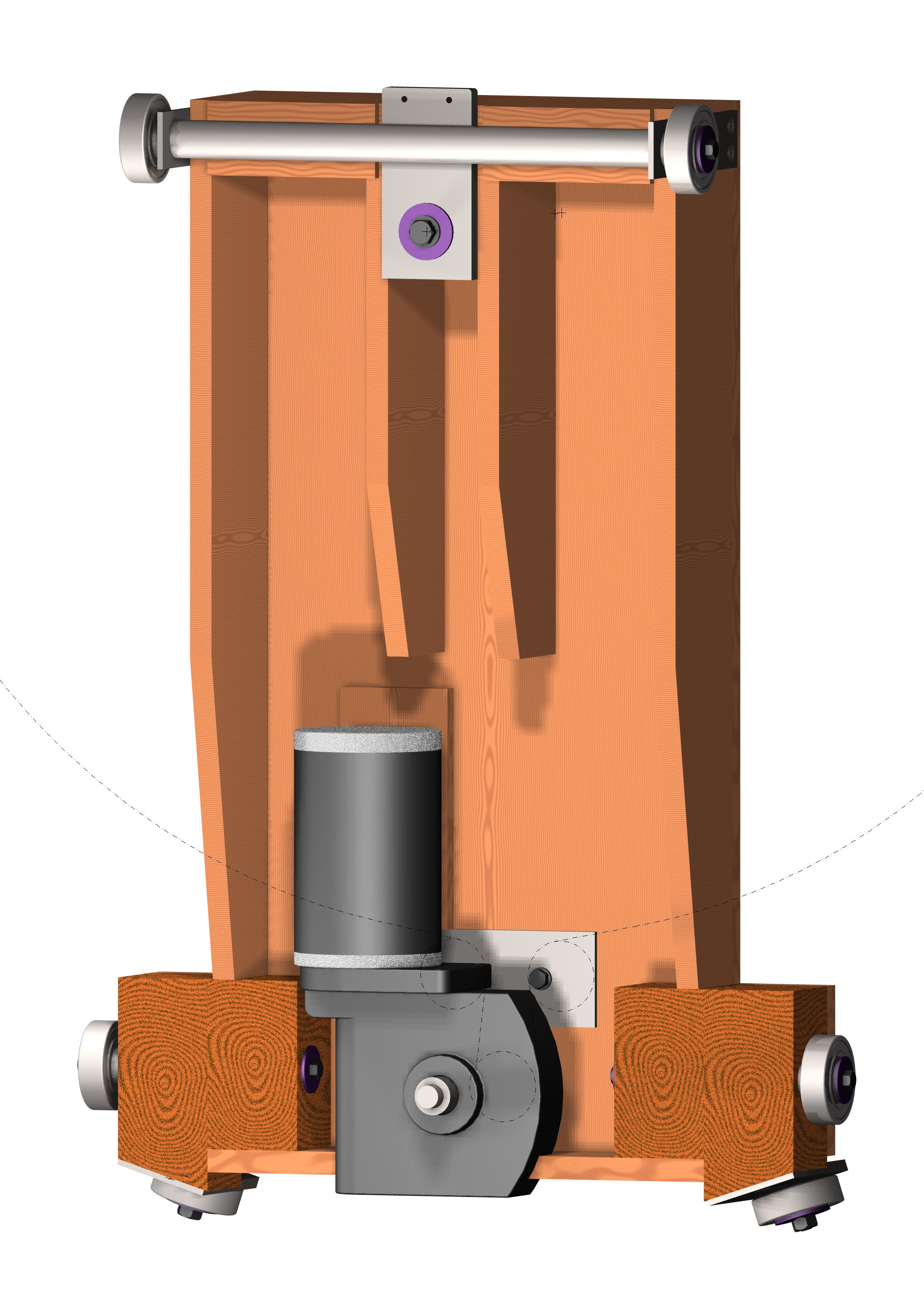
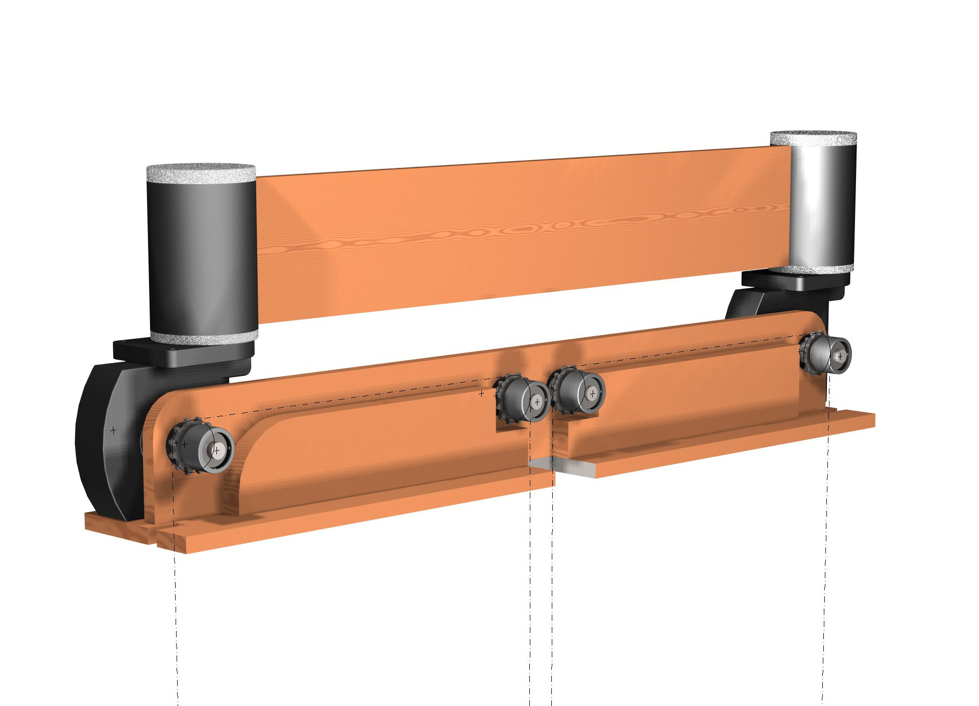
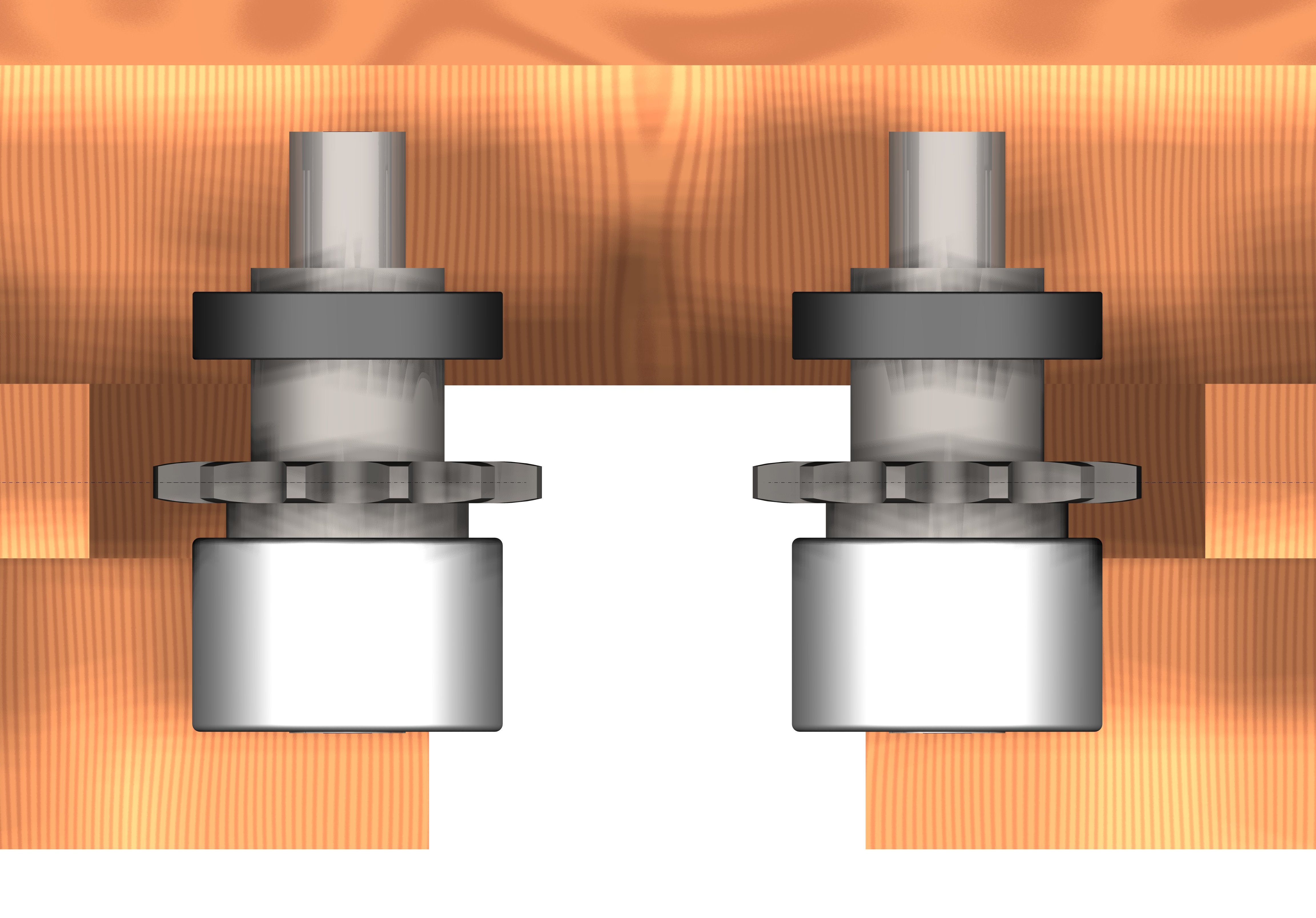
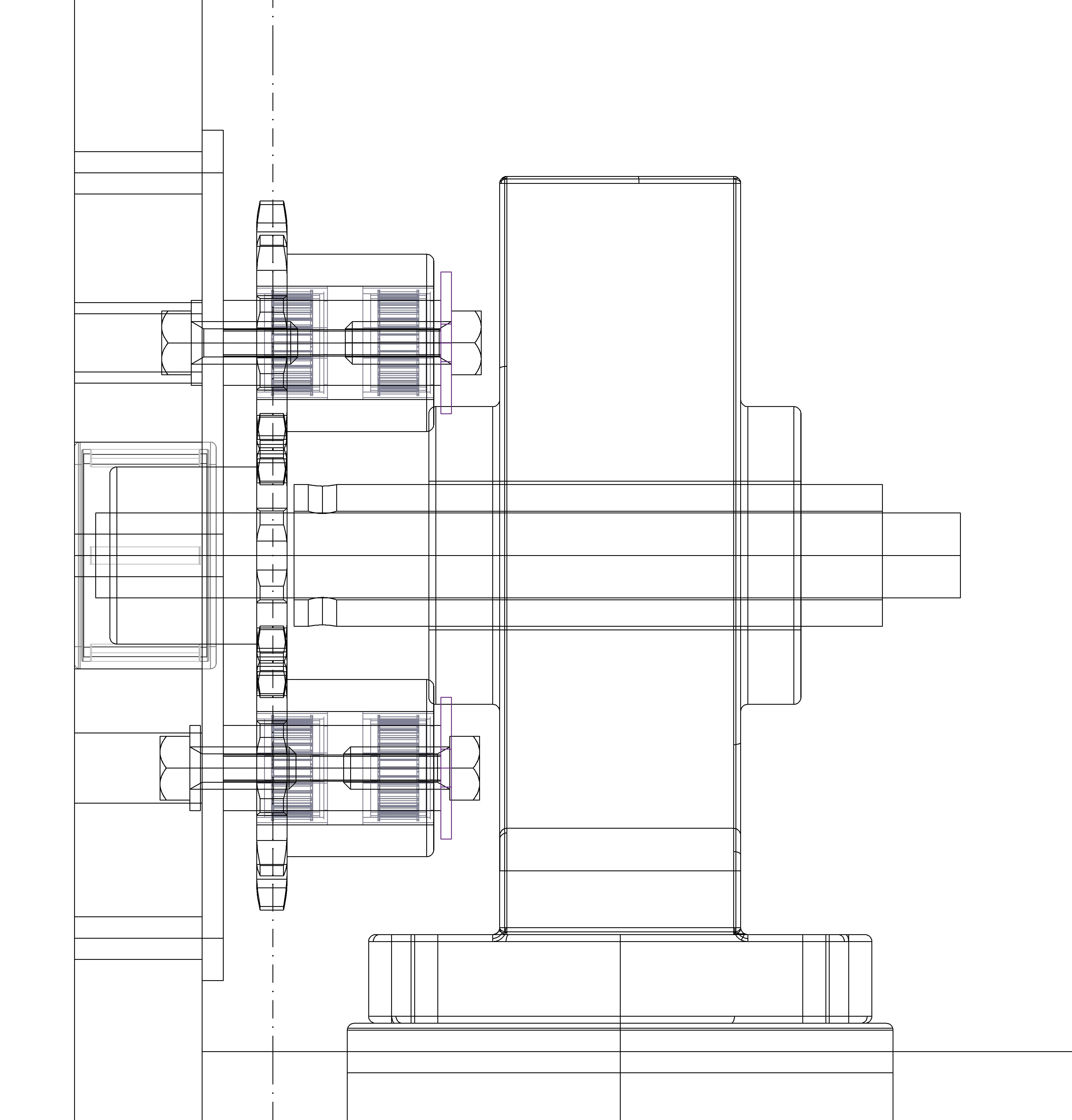
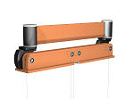
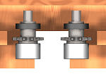
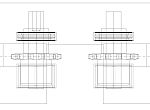
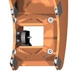
Heave Drive
Mounted at the top of the wall brace, again 3/8" pitch simplex
roller chain (might be better with duplex chain) carries the
cockpit and is driven by the 2x200W motors. The heave feedback
potentiometer is mounted on one of the idler sprocket spindles.

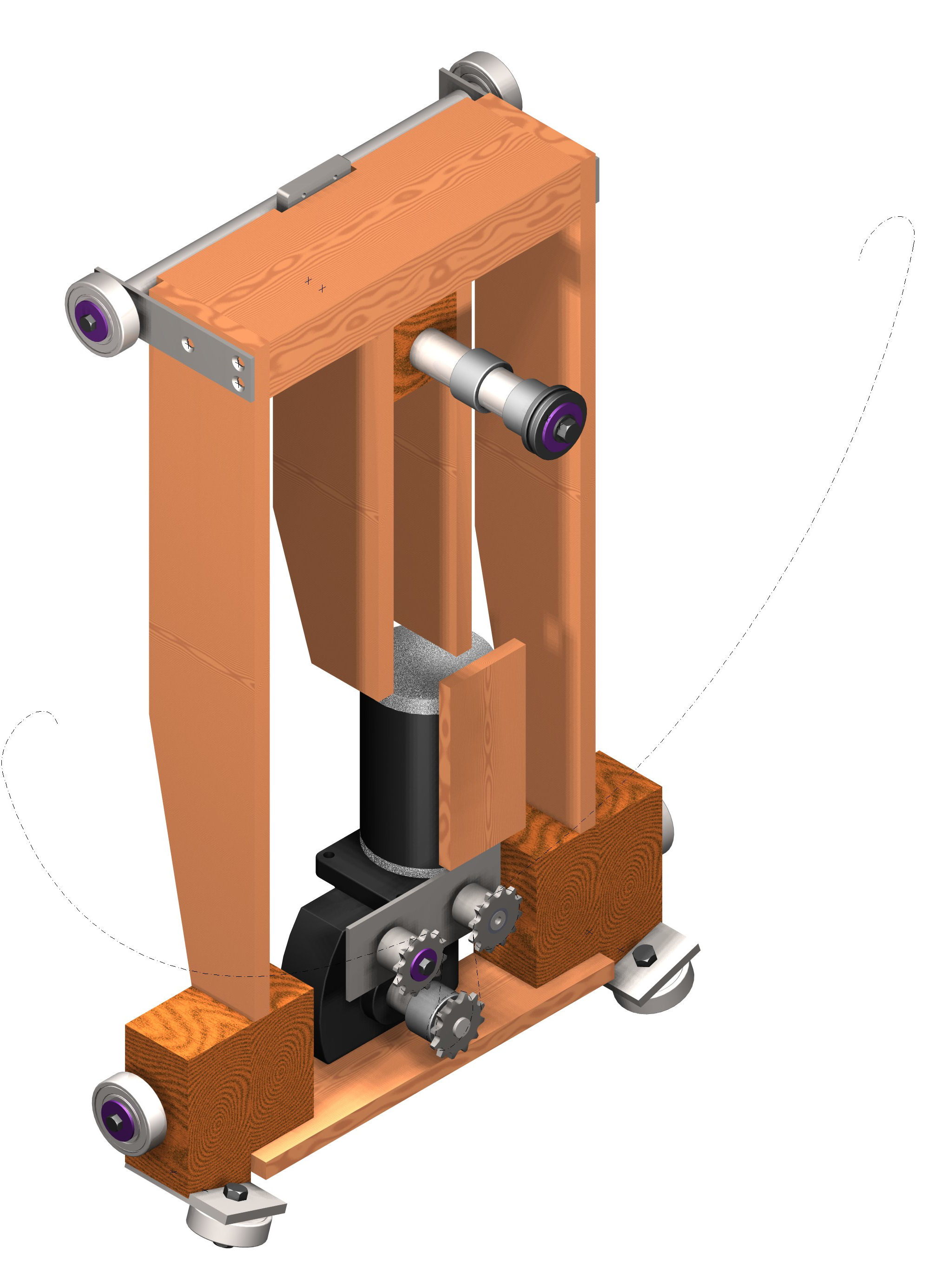
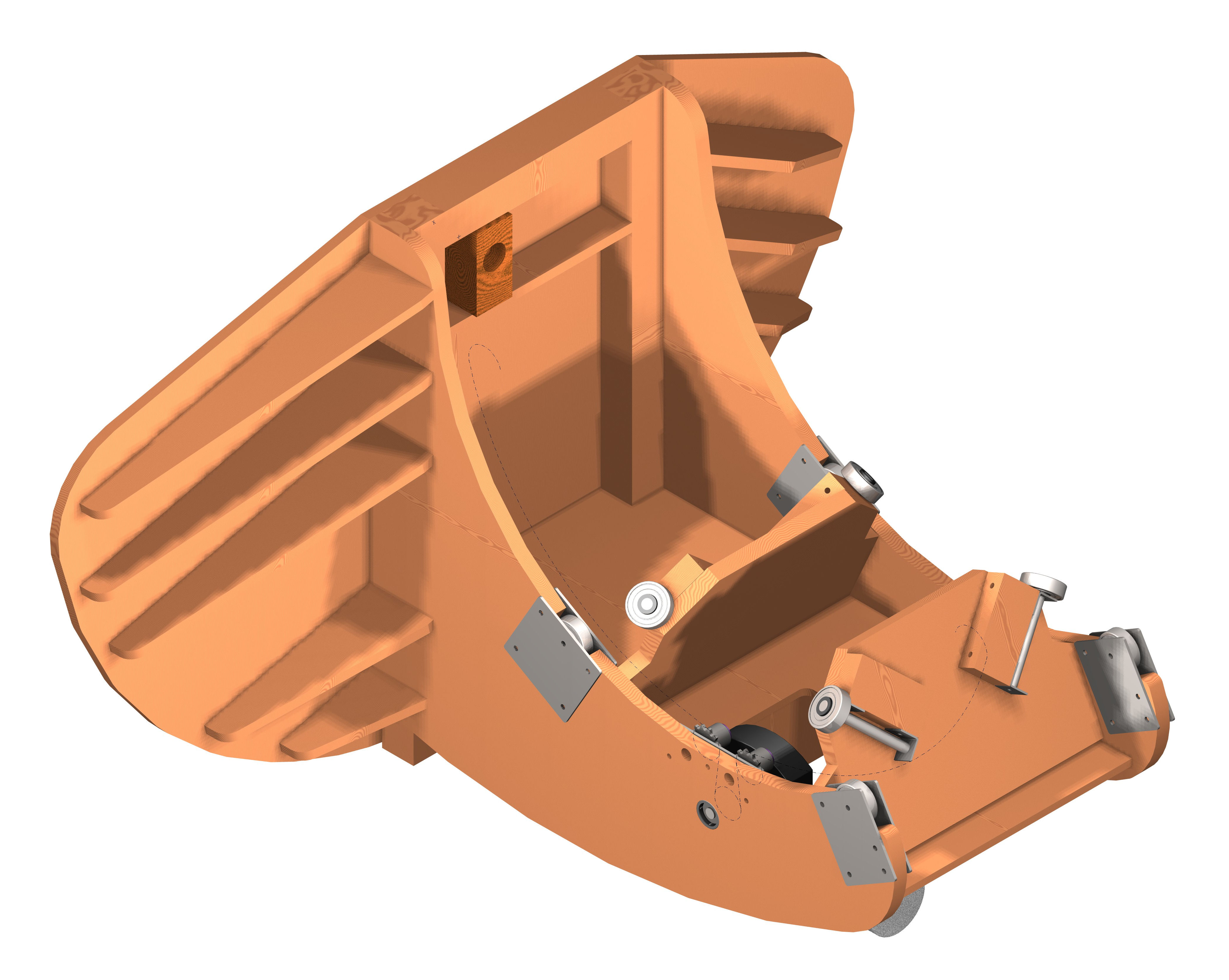
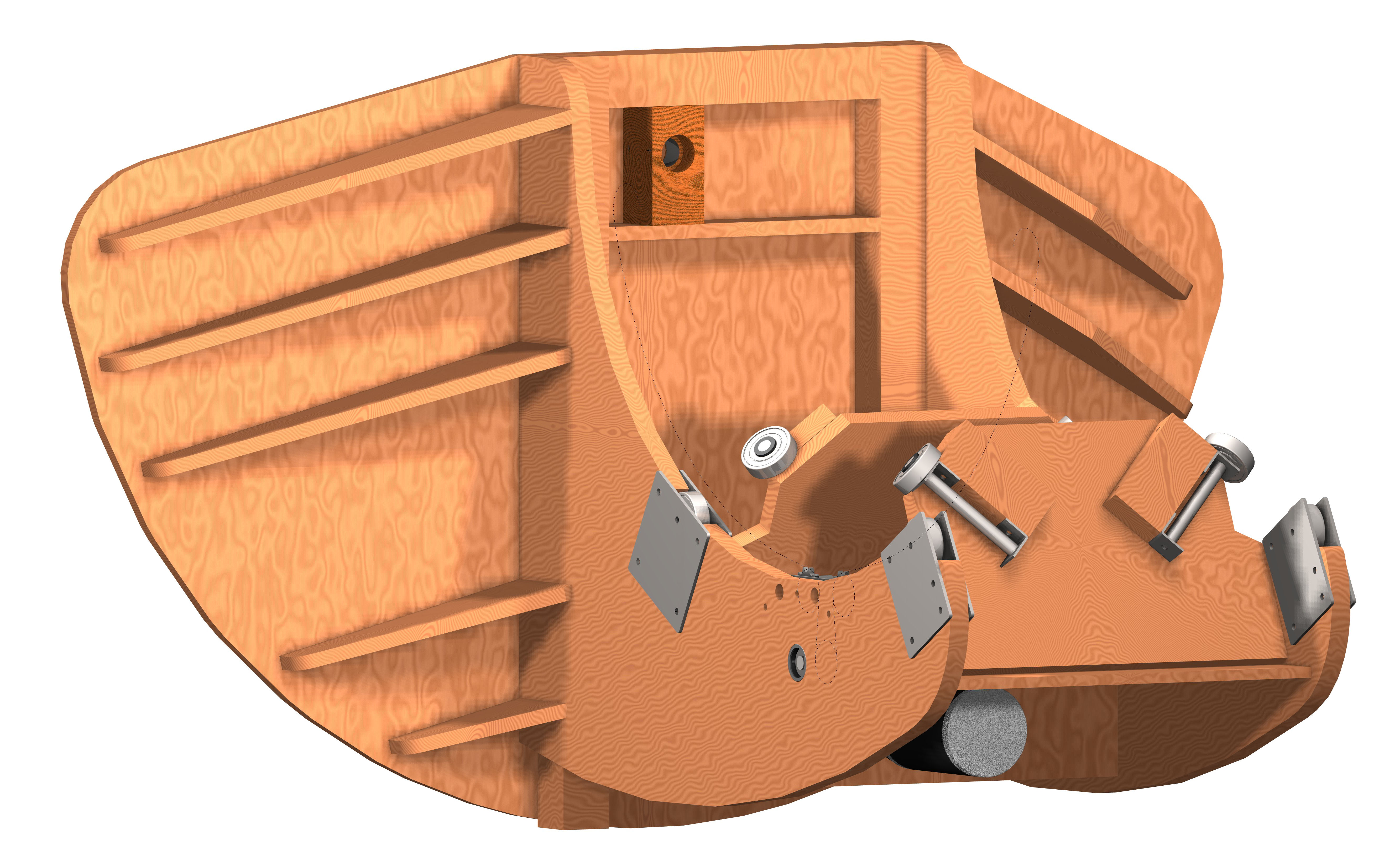
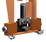
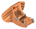
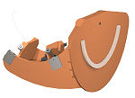
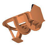
Cockpit Cradle
Key elements are the angles rollers which prevent fore-aft
movement of the cockpit - these are heavily loaded when in use
and need to be rigidly supported.
3/8" pitch simplex roller chain to drive the cockpit roll
movements.
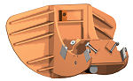
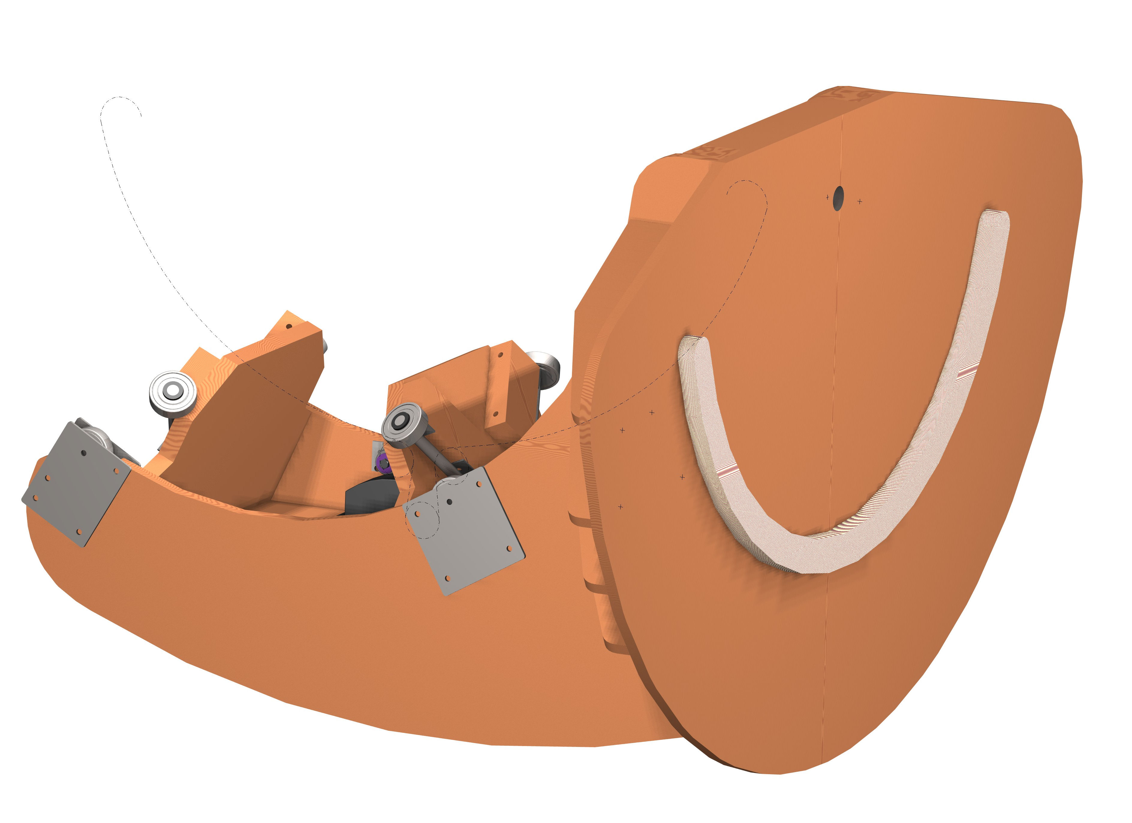
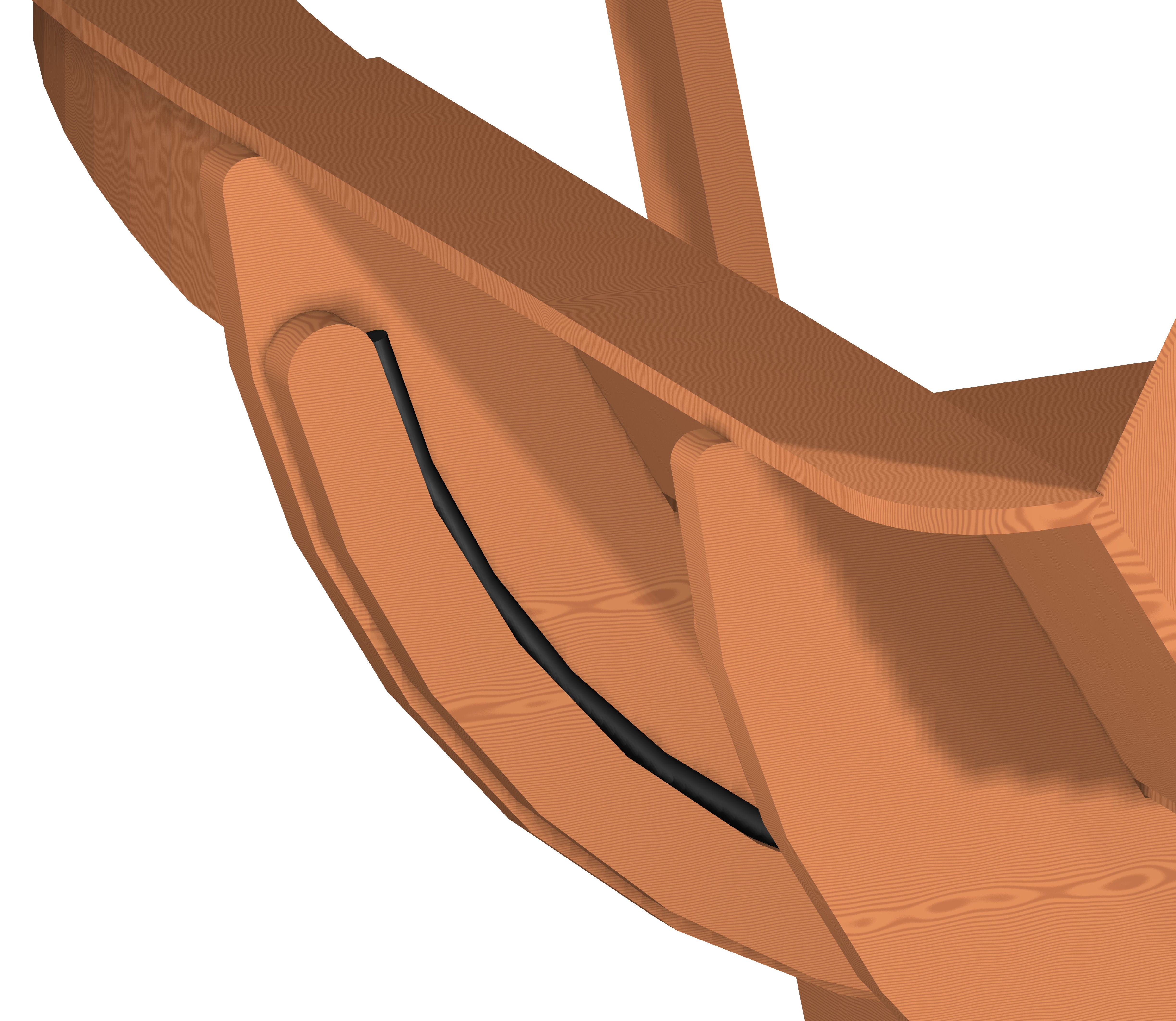
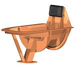
Cockpit
Light-weight timber structure. Key part is the curved running
surface for the fore-aft movement constraining rollers on the
cradle. I used Ř12mm steel reinforced electrical power cable for
this (shown in black) bonded to the curved plywood formers.

© This site is
copyrighted, If you'd like more information or have any
comments please contact me at