Previous
Contents
Next
4. Force Feedback Tuning Procedure
IMPORTANT - force adjustment
should be done AFTER the system is fully setup and commissioned -
see the project build documentation.
Actual levels of force output will
be different for different flight control designs - it is not
possible to have a single configuration file that will work for all
installations. Additionally some users may not use some of the force
features, so you may wish to adjust the settings to suit your own
preferences.
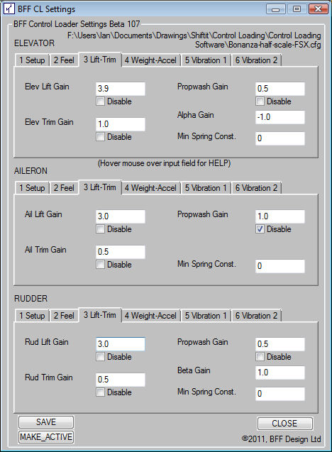
The best way to adjust the
settings is to disable ALL force components other than the one
you are working on (use the check boxes below each setting to
enable/disable it). Then place and pause the aircraft in a flight
situation which will generate the required loading conditions. The
gains associated with the force component can then be adjusted and
made-active in the Settings application and tested by engaging the
force feedback through the CL Software.
The main force components and
relevant flight situations are below - it may be helpful to make the
adjustments in the order given. Note that there are SEPARATE
settings for each control axis.
Once the basic settings have been
made check the response over a range of flight conditions and adjust
as required.
-
Main Lift Force:
Enable the main lift force. Disable all trim, propwash, alpha,
weight and vibration force elements. Place and pause the
aircraft in straight and level flight at the normal cruising
speed for the aircraft. Adjust the Lift Gain in Tab 3 and
click the Make-Active button, then Engage the
force output to test the force levels.
Increasing the gain will increase the stiffness of the controls.
The stiffness will also vary with varying airspeed - but setting
at normal cruise speed should give a reasonable benchmark at the
upper end of the loading. The AS_Exp parameter in the settings .cfg
file sets the power to which the airspeed is raised in the force
calcs. So AS_Exp=2 sets stiffness proportional to airpseed
squared and may be suitable for GA aircraft. AS_Exp=1 will make
stiffness linearly proportional to airspeed and may be more
suitable for fly-by-wire heavy or fast jets.
If the force progress bars routinely go to maximum during NORMAL
control displacements then it is likely that the overall force
output of the system is not adequate. Re-assess the motor
transmission gearing ratios, check the power supply voltages
when under load (is the supply capable of delivering the current
required), check you are not running on a 12V supply with the
default card 1/2 scale output programming.
-
Trim Force:
Enable the trim lift force. Disable all propwash, alpha, weight
and vibration force elements. Place and pause the aircraft in
straight and level flight at the normal cruising speed for the
aircraft. Adjust the Trim Lift Gain in Tab 3 and click
the Make-Active button, then Engage the force
output to test the trim adjustment direction and the force
levels. The trim direction can be reversed by reversing the sign
of the gain.
Note that without airflow over the control surfaces there will
be no trim forces generated.
-
Alpha (Angle of Attack
Effects):
Enable the Alpha effects by specifying an Alpha Gain of
-1.0. With the main lift force and trim force settings made
place the aircraft in straight and level trimmed flight at the
normal cruising speed for the aircraft. With the flight active
Porpoising the aircraft should induce short surges in the
centring forces at the elevator as the aircraft angle of attack
varies with the nose-up, nose-down motion of the aircraft.
If the Alpha Gain value has the incorrect sign the force
variations will be felt as reductions in the centring forces as
the aircraft porpoises.
Adjusting the Alpha Gain will also affect the magnitude
of the out-of-trim forces that arise when the aircraft airspeed
changes and its pitch angle adjusts to the new airspeed.
-
Prop-Wash Loading:
Enable the Propwash loading. Disable all weight and vibration
force elements. Place the aircraft stationary on the runway,
apply the brakes. Apply engine power to generate airflow over
the control surfaces - this will induce propwash loading on the
axis concerned which will drive the controls towards mid
position. Assess the strength of this loading and adjust the
Propwash Gain to suit.
-
Elevator Weight Effects:
If you wish to feel static (or dynamic) weight effects on the
elevator uncheck the Balanced checkbox under Tab 4. Place
the aircraft stationary on the runway. If propwash loading is
active make sure the engine power is removed.
When the FFB is engaged the elevator should pull forward to
simulate the static weight of the controls. Adjust the Mass
Gain to tune the force level. Reversing the sign of the
Mass Gain value will reverse the static loading.
-
Engine Vibration:
Under Tab 6 untick the lower checkbox to enable the engine
vibration effects. With the aircraft stationary on the runway
and brakes applied throttle up the engines. The engine vibration
effects should be felt through the controls- they will vary in
magnitude with the engine thrust and in frequency with the
engine rpm.
Adjust the Gains to tune the vibration effects to set the
maximum vibration against maximum engine thrust.
The upper checkbox can be unchecked to enable a minimum engine
vibration which will always be on when the FFB is engaged.
Adjust the adjacent Gains to set a low level minimum engine
vibration effect.
-
Runway Vibration:
Temporarily disable the engine vibration effects.
Under Tab 5 untick the lower checkbox to enable runway vibration
effects. Place the aircraft on the runway and proceed with
take-off; pause the sim when you reach your maximum takeoff
speed before the aircraft leaves the ground.
Adjust the Gains to set the runway vibration magnitudes and
frequency. They will vary in magnitude and frequency with runway
speed. Once set check the effects over the full raange of runway
speed to check both low and high speed feel.
-
Stall Vibration:
Temporarily disable the engine vibration effects.
Under Tab 5 untick the upper checkbox to enable stall vibration
effects. Place the aircraft in a stall and pause the sim.
Adjust the Gains to set the stall vibration magnitudes and
frequency. They will vary in magnitude with relative angle of
attack so the stall vibration should begin as the aircraft
approaches stall.
NOTE if your mechanical controls
have more inertia than the flight yoke designs on the web site the
vibration force cap levels may need to be raised. This can be done
by altering the flash programming on the card. Please contact me for
information and instructions if you wish to do this.
Previous
Contents
Next
|