Previous
Contents
Next
Appendix J.
CL Controller App - Input UDP Data Format
|
BFF CL Controller
software
DOWNLOAD:
Now included in main CL software download
USER GUIDE:
Quick User Guide |
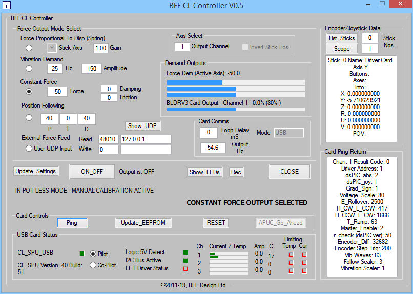
The
CL Controller is a new
app which combines the loading test functions available in
the Driver Test App with a new operating mode which accepts loading command data from 3rd party
apps via UDP.
This allows 3rd party apps to
control the CL drive cards via the CL Controller. Applies to
CL_SPU_USB and BLDRV3 cards only.
NOTE the CL Controller can not
drive the same CL_SPU_USB card at the same time as the main CL
Software. So if the CL Software AND the CL Controller are to be used
at the same time then two CL_SPU_USB cards with their own BLDRV3
drives are required.
Installation:
The CL Controller is included in
the main CL software download zip in the Driver Test App folder.
Operation:
NOTE: if the CL Controller is
being used to provide specialised axes at the same time as the main
BFF CL Software is driving the main control axes then the CL
Software CL_SPU_USB card should be jumper set as "Pilot", and the CL
Controller should connect to the jumper set Co_Pilot CL_SPU_USB
card. Parameter CP_Ignore should be set =1 in the Background.ini
file to instruct the main CL Software to then ignore any Co-Pilot
CL_SPU card.
The CL Controller should be
running and the UDP Input radio button selected to make the UDP data
mode active.
When running in UDP input mode, the
CL Controller will
listen for UDP data on the Port and IP Address specified in the
CL_Controller ini file (also shown on the GUI). You must write your own application to send valid
loading data. The data format is shown below.
WARNING - Improperly
formatted or controlled user loading input data can produce erratic
or uncontrolled force and movement outputs at the driven flight
control motors - you must thoroughly test your UDP data "feeder" application before
making the card output live to connected flight controls.
Use the progress bar displays on
the CL Controller to monitor the output force demands that result
from your Feeder application before driving live flight controls. A UDP data view window is also provided to allow visual inspection of
received data packets.
UDP Data Formats:
When in UDP Input mode the CL
Controller looks for loading control data in 180 byte packets
received by UDP on the Port and IP Address specified in the
CL_Controller.ini config file (parameters Port
and IPAddress in the [Comms] section).
The CL Controller will return a 50
byte response packet on each input packet receive. This UDP return
will be via port Port+1 to the IP Address and Port specified
by the feeder app within the 180 byte input packet.
The 180 byte input packet format is:
| Byte
Offset |
Name |
Type |
Description |
| 0 |
Packet
ID |
UInt |
Each data packet should have a
unique +ve integer ID. Usually this is a simple indexing
packet counter. |
| 4 |
Loading
Engage Command |
UChar |
=0 loading disengage, =1 loading
engage Note these will be
overridden by the Engage/Disengage button on the CL
Controller.
On the ON/OFF transition the CL
Controller will ramp up/down the loading.
On the ON transition CL Controller
will also ping the cards to determine status before ramping
up the loading - this will cause a momentary delay to the
load engage. |
| 5 |
Feeder
PC IP Address |
15 byte
String |
IPV4 format IP Address of the
Feeder App's network location to which the 50 byte return
packet will be sent. If the Feeder App and CL Controller App
are running on the same PC then this can be a loop-back
address, eg 127.0.0.1 Pad
unused trailing bytes with NULLs |
| 20 |
Return
Port |
UShort |
Port to which the return packet
will be sent.
=0 to disable the return packet
send. |
| 22 |
Position Following Engage |
UChar |
Position Following Engage
Bitwise as follows:
bit0 - enable axis 1 position following, 0 = off, 1 = on
bit1 - enable axis 2
bit2 - enable axis 3
bit3 -
bit4 -
bit5 - position following ALWAYS-ON for all axes (eg for
Slave station
operation)
bit6 - (heli-trim on/off)
bit7 - (enable heli-control mode) |
| 23-29 |
Spare
Bytes |
|
pad with NULL |
| |
|
|
3 x 50 byte sections follow; 50
bytes for each loading axis.
Axis 1 (Elevator) |
| 30+0 |
Fixed
Force |
Float |
Fixed force component: +/- 100%
+ve is drive in +ve drive direction of
card/motor |
| 30+4 |
Spring
Force Coefficient |
Float |
Spring force component as
stiffness coefficient: typically 0-10.0
A Coefficient of 1.0 will generate
100% force at 100% deflection. Only +ve values allowed and
will generate a force opposing displacement -ie always a
return to mid position. |
| 30+8 |
Friction Coeff |
Short |
+/- 127, typically in range +/-10.
+ve to oppose movement |
| 30+10 |
Damping
Coeff |
Short |
+/- 127, typically in range +/-10.
+ve to oppose velocity |
| 30+12 |
Vibration Channel 1 Base Freq (Hz) |
Short |
5-100 typically
Channel 1 is an engine mix |
| 30+14 |
Vibration Channel 1 Amplitude |
Short |
5-100 typically.
Vibration mix is
also scaled and defined by card EEPROM settings |
| 30+16 |
Vibration Channel 2 Base Freq (Hz) |
Short |
5-100 typically
Channel 2 is a runway mix |
| 30+18 |
Vibration Channel 2 Amplitude |
Short |
5-100 typically.
Vibration mix is
also scaled and defined by card EEPROM settings |
| 30+20 |
Vibration Channel 3 Base Freq (Hz) |
Short |
5-100 typically
Channel 3 is a stall mix |
| 30+22 |
Vibration Channel 3 Amplitude |
Short |
5-100 typically.
Vibration mix is
also scaled and defined by card EEPROM settings |
| 30+24 |
Position Following P Term |
Short |
0-127.0 typically 20 to 60
Proportional term of position
following PID algorithm |
| 30+26 |
Position Following I Term |
Short |
0-127.0 typically not used in CL
drives (use 0.0) Integral term of
position following PID algorithm |
| 30+28 |
Position Following D Term |
Short |
0-127.0 typically 20 to 60
Derivative term of position following
PID algorithm |
| 30+30 |
Position Following Set Point |
Float |
0-100.00%
Demanded position when in position
following mode. Mid position is 50%, full displacement in
drive direction is 100%
(Corrected 5/20,
previously stated as +/-100% range) |
| 30+34 |
Breakout Rate |
UChar |
Integer value 1, 2, 3 or 4
Sets the onset rate of the breakout
force |
| 30+35 |
Breakout Amplitude |
UChar |
0-100 typically 10-20
Sets the magnitude of the breakout
force |
| 30+36 to
+49 |
Spare
Bytes |
|
pad with NULL |
| |
|
|
|
| 80+0 to
+49 |
As
Above |
|
Repeat for Axis 2 (Aileron) |
| |
|
|
|
| 130+0 to
+49 |
As
Above |
|
Repeat for Axis 3 (Aileron) |
UChar = 8 bit (1 byte) unsigned integer (value
0-255)
UShort = 16 bit (2 byte) unsigned integer
Short = 16 bit (2 byte) signed integer
UInt = 32 bit (4 byte) unsigned integer
Int = 32 bit (4 byte) signed integer
Float = 32 bit (4 byte) floating point number
The frequency of data packets
should typically be about 50Hz to match the command rate of the CL
Controller to the drive cards
You should experiment to obtain processing rates to suit your
application. If the data packets arrive faster than the CL
Controller can process them it will simply drop unused packets.
The UDP_Display button on the GUI
can be use to display the incoming UDP data.
UDP Return Packet Format:
The CL Controller will return a 50
byte response packet on each input packet receive. This UDP return
will be via port Port+1 to the IP Address and Port specified
by the Feeder app in the 180 byte input packet.
The 50 byte return packet format is:
| Byte
Offset |
Name |
Type |
Description |
| 0 |
Packet
ID |
UInt |
Each return data packet has a
unique +ve integer ID. This is a simple indexing
packet counter. |
| 4 |
Last
Input Packet ID |
UInt |
Packet ID of last used 180 byte
input packet |
| 8 |
Force
Enable Status |
UChar |
Current loading ON/OFF status.
0 = OFF, 1 = ON |
| 9 |
Drive
Axis 1 Status |
UChar |
dsPIC_Joy1 status byte
=0 - axis not calibrated
=1 - axis calibrated
=3 - axis has moved out of calibrated range
>= 4 - unknown dsPIC_Joy error |
| 10 |
Drive
Axis 2 Status |
UChar |
dsPIC_Joy2 |
| 11 |
Drive
Axis 3 Status |
UChar |
dsPIC_Joy3 |
| 12 |
Card
Auto-Calibration Status |
UChar |
Bit significant -
bit0 - MUST = 0 for bits below to be active
bit1 - ELEV awaiting APUC go-ahead
bit2 - AIL awaiting APUC go-ahead
bit3 - RUD awaiting APUC go-ahead
bit4 - ELEV APUC movements in progress
bit5 - AIL APUC movements in progress
bit6 - RUD APUC movements in progress
bit7 - 0 |
| 13 |
Card
Condition |
UChar |
Bit significant -
bit0 - 0
bit1 - ELEV card is over-temperature limiting
bit2 - AIL card is over-temperature limiting
bit3 - RUD card is over-temperature limiting
bit4 - ELEV card is over-current limiting
bit5 - AIL card is over-current limiting
bit6 - RUD card is over-current limiting
bit7 - 0 |
| 14-16 |
Spare
Bytes |
|
NULL |
| 17 |
Axis 1
Position |
Float |
Axis 1 position in range +/- 100%,
mid = 0 |
| 21 |
Axis 2
Position |
Float |
Axis 2 |
| 25 |
Axis 3
Position |
Float |
Axis 3 |
| 29 |
Axis 1
Torque |
Float |
Axis 1 torque in range +/- 100%
(of available output after card internal voltage scaling) |
| 33 |
Axis 2
Torque |
Float |
Axis 2 |
| 37 |
Axis 3
Torque |
Float |
Axis 3 |
| 41-45 |
Spare
Bytes |
|
NULL |
| 46 |
Packet
ID Repeated |
UInt |
See offset 0 |
Test Feeder Application:
The download zip package contains
a test "Feeder" application which can be used to confirm UDP comms
with the CL Controller. The Feeder application can pull position
data from the x, y & z axes of the joystick specified in the
Sender.cfg file and use this to set
load or stiffness components to send to the CL Controller. It
will send the data to the CL Controller using correctly formatted UDP packets. If UDP comms are
active the data will appear at the CL Controller....
The test Feeder app will also
display returned response packets from the CL Controller if the UDP
comms are correctly configured.
The port and IP address settings
for the Feeder should be made in the Sender.cfg file.
This is intended for checking
UDP comms only - DO NOT use this facility to control live flight
controls.
Demonstration Steering Tiller Feeder Application:
A demonstration feeder app is also
provided in the download zip which provides simple loading for a
heavy jet steering tiller axis.
Further information here....
Comments:
The data components used in the
data packets are designed to suit control loader type applications.
In particular the spring rate parameter (spring force coefficient)
should be used when loading proportional to control displacement is
present. The fixed force parameter should be used for slower
changing forces only. In order to maintain stability in the drive it
is important to minimise lag between axis position changes and the
responding torque demand applied to the motors when there is
a possibility that the position can change rapidly. The most
critical type of loading in this regard is force that changes
directly with stick displacement such as aerofoil lift forces. By
using a spring rate term the critical calculations for this type of
loading can be carried out onboard the BLDRV3 cards and so minimise
the lag between position feedback and torque response. These onboard
calculations are carried out once every 2ms (ie at 500Hz) and ensure
that the torque demand output "keeps up" even with fast changing
stick position and so ensures stability of the drive by preventing
unstable oscillations from developing.
The principal applies to other
applications in which there is a significant force component which
changes directly in response to axis position change.
Updates:
V0.91 adds a new window which
displays monitoring data for the APUC movements of the controls.
This requires recent BLDRV3 card firmware to operate.
If you find any bugs or strange
behaviours in the beta version then please let me know.
Previous
Contents
Next
|