Previous
Contents
Next
3. Operation
To run the software double
click on the motion driver .exe in your installation directory or on
a shortcut setup to point at the .exe.
The driver window has
a number of buttons - each has a pop-up tool tip which provide more
details of the button function. The buttons are -
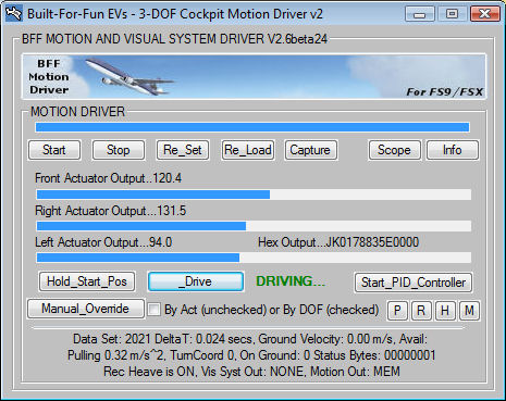
UPPER BUTTONS
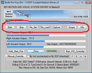
Start - The
motion driver reads its run settings from a .bff configuration file,
the Start button will open a file selection window and then proceed
execution of the driver operation with the settings from the
selected config file. See the settings
section for details of the .bff configuration file parameters.
A number of default .bff
config files are included in the download zip package. Use the one
for your platform type as a start for your set up. See the
settings section for information on
settings adjustments that will need to be made.
Stop - stop and close the driver (or hit programmed STOP hot
key).
Re-Set - re-start with the current configuration
file.
Re-Load - re-load a new configuration file.
Info
– toggle the full
driver window with information.
Capture
- capture the maximum and minimum flight accelerations and pitch and
roll angles.
The
Flight Data Limits Capture window allows you to capture the recent
maximum and minimum values of key flight parameters. These include
forward, lateral and vertical accelerations and pitch and roll angles
and good knowledge of these is needed to set the configuration
settings for the driver. Use the capture button to capture the
accelerations associated with key flight events such as takeoff
accelerations, braking decelerations, vertical lift-off
accelerations, turbulence induced accelerations etc etc. With this
information you will be able to better judge the acceleration cap
levels and scaling to the platform movement range. NOTE that the acceleration
values shown are factored by the scaling parameters specified in the .bff
configuration file.
Scope – activate the built-in virtual
oscilloscope to display real-time traces of the motion cues. The
traces are of the motion cues by DOF before any mixing or management
processing is done by the driver unless the Scope_Mode=1 parameter
is set in the .bff config file when the outputs are then by actuator. The output will be active so long
as the flight sim is not paused, this will allow the active motion cues
to be displayed even with the driver on Hold.
The oscilloscope can be used with the in-program cue
setting windows (see below) to assess adjustments to the motion cue
settings whilst the driver is running and so allow the effects of
changes to be assessed rapidly. IT IS RECOMMENDED THAT THIS IS
DONE WITH THE PLATFORM DRIVE INACTIVE!
The virtual oscilloscope is implemented using Michael
Bernstein's excellent Software Oscilloscope DLL – see his web
site at http://www.oscilloscope-lib.com/
for more details. The traces can be manipulated on the scope using
the buttons provided as is normal for any oscilloscope.
LOWER BUTTONS
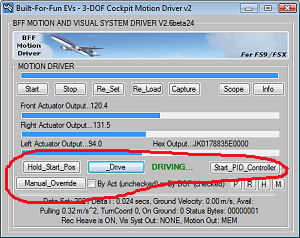 Drive - engage active platform drive. The motion cue output
will ramp from the current parked/start position to the current live position
from the flight sim. Drive - engage active platform drive. The motion cue output
will ramp from the current parked/start position to the current live position
from the flight sim.
Hold_Start_Position - return the platform to its
start/parked position. In this mode a constant
stream of position demands are output set to the hold position of the
platform actuators.
Start_PID_Controller - start the BFF PID Servo
Controller application – this will require the data output mode
to have been set to MEM, otherwise the Servo Controller will not start. For more
details see the PID Servo Controller section.
Manual Override - manually override the position
demand outputs from the driver.
This
will open the Override window which has three sliders – one for
each output channel/DOF of the driver. Moving a slider will adjust
the value of the position demand output for that Actuator or DOF
within the full 0-255 range if the “Enable” check
box has been checked for the Actuator. If the “Follow Act 1”
box is checked than all three sliders will follow the position of the
Actuator 1 slider.
If the “By DOF” checkbox is checked on the
main UI the output will be by DOF and not by individual actuator. For
coupled drive platforms this will result in all the actuators moving
as required for the selected DOF.
WARNING – Because this feature is intended
as an aid to establishing the working range of a platform the sliders
operate within the FULL 0-255 position output range. Use with
great care – if your platform drive is active the platform
may move suddenly in response to movements of the sliders, if you
demand a position out-with the physical working range of your
platform the platform will drive onto its end stops. Trial this function with
the platform drive INACTIVE to get a feel for its operation.
The sliders can be moved with the mouse or more
sensitively with the left/right keyboard arrows.
CUE SETTING BUTTONS
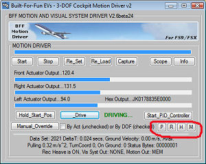 In-Program
Cue Adjustment Settings – there are four small buttons
provided - P, R, H and M to open the settings
windows for the Pitch, Roll and Heave degrees of freedom and the actuator mix
proportions for Mode=2 set ups. For details of the individual settings see the
pop-up tool tips. In-Program
Cue Adjustment Settings – there are four small buttons
provided - P, R, H and M to open the settings
windows for the Pitch, Roll and Heave degrees of freedom and the actuator mix
proportions for Mode=2 set ups. For details of the individual settings see the
pop-up tool tips.
Opening either of the three settings windows will send
the driver output back to the “hold” position to disable
live output of the cues whilst the settings are being adjusted.
To adjust a setting make the change in the appropriate
text box and click Use. This will make the adjusted settings
active in the driver but will not save them to file.
To save the new settings to the active configuration
file click Save.
On the Pitch and Roll windows a simple settings wizard is
included. This allows easy setup of the main cue range and scaling parameters
(not the noise and washout filter time constants) to match the cue output to
specified g-force and/or aircraft orientation ranges - follow the instructions
in the pop-up tool-tips.
IMPORTANT – Take great care when making
changes to the cue settings as they can directly impact on the motion
range. It is recommended that the adjusted cue output is viewed in
the Virtual Oscilloscope and its stability assessed BEFORE the driver
is put back in Drive mode and the platform made active.
HOTKEYS
Drive, Hold and Stop HotKeys and/or joystick hot-buttons can be programmed
using the settings in the .bff configuration file. See the
settings section.
\+B (Backslash plus B) – will toggle the pre-recorded
light turbulence heave motion on or off – the MSFS driver
starts with this ON. The effect can be scaled or disabled completely
by adjusting the value of the Turb_Scalea parameter in your .bff
configuration file (set =0 to disable).
\+R (Backslash plus R) – will initiate a new heave
motion recording run. This will last two minutes and will end by
closing the driver and writing the newly recorded data to the
BFF-Turb.txt file in the driver's working directory. This will
overwrite the existing file, so back it up if you want to keep the
original data supplied in the driver zip package. To use this
facility set up a flight in your aircraft of choice and fly straight
and level – best to use the auto-pilot. Set the weather
conditions to remove all weather effects except an additional
turbulence level – you chose what level of turbulence in the
User Defined Weather settings. The aim is to get a 2 minute run with
turbulence induced heave movement alone which can later be
superimposed on the live heave motion cue.
Previous
Contents
Next
|