|
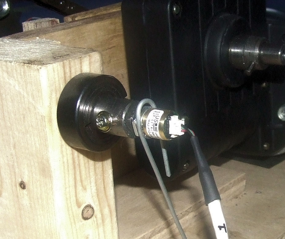
MA3 Encoder
fitted to the end of a drive shaft |
Summer 09 - A ready built
higher speed Signal Processor card is now available to
buy - this does away with all the breadboard electronics and
fiddly wiring - see the 40SPU-1 card
page for up-to-date details. The signal processor card
includes support for both US Digital MA3 feedback
encoders and potentiometer feedback.
As I described on the
SPU page the PID Servo Controller software uses
Proportional-Integral-Derivative algorithms to calculate the
motor speed demands required to drive the motion platform
through the Signal Processor Unit. The Derivative term is
the most difficult of the three control terms to use because it is very
susceptible to noise on the position feedback signals.
I've been experimenting with a lower noise
alternative to the normal resistive type feedback
potentiometers I've used on all the motion platforms so far
and these are these
US
Digital MA3 position encoders. They use non-contacting
magnetic position sensing methods to produce an output of
absolute rotational position and produce much less noise on
the feedback signal.
They are available with voltage or pulse
output signal formats and I've used the 12bit PWM
output versions which produce a continuous series of pulses
at about 250 Hz with pulse lengths that vary between 1 and
4096 μs in proportion to the absolute shaft position. Their electrical
travel is 360° but interestingly have no mechanical limit
and the electrical output returns to zero and repeats when
the rotation passes through 360°.
|
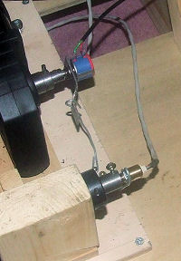
MA3 Encoder
alongside my original position feedback
potentiometer |
The MA3 encoder's PWM output can be read by
the SPU's 28X1 Picaxe chip using "pulsin" commands. This can
achieve a resolution down to 2.5 μs when a 16MHz resonator
is used. On my tests I've found that the feedback signal
seems to be clean right down to the 2.5/4096 resolution of
the 28X1's pulsin command. With the potentiometers I used
previously (and converting to a comparable scale) the noise
level was about 14/4096 so a distinct improvement.
The 28X1 chip can't run much faster that
16MHz so I'll have to wait for the release of the
forthcoming 28X2 from PICAXE before I can read the MA3
position output at full 12 bit resolution which will then
give me a resolution of 1/4096 on the position feedback
signal.
Even with the 28X1 limitations I've found
that the improved position feedback signal quality does
allow more to be achieved with the Derivative terms in the PID
Servo Controller setup. This has allowed me to add more sharpness to the system response to
give better
handling of sudden acceleration events such as touch down
bumps. The higher speed 28X2 chip will allow more to be
achieved when it comes available.
SPU 28X1 Chip Programming
If you are interested in trying the MA3
encoders with the Basic SPU you will need to re-flash the 28X1
chip with a new .bas program. The program
SPU_I2C_16_MA3_REV2.BAS reads the position data as pulse
inputs on chip pins 11 through 13 to which the encoder data
outputs must be connected. Using this will involve a
small modification to the existing single chip SPU wiring
because the current potentiometer feedback is not to these
pins. A 16MHz resonator should be fitted.
The encoders can also be used with the
Enhanced Speed SPU to
further improve the control system performance.
You will also need V2 of the PID Servo
Controller software and also V2 of the BFF Motion Driver
software. V2 of the PID Controller is programmed to read the
higher resolution data sent by the 28X1 flashed with the
above .bas program - this output will NOT be recognised by
v1 versions of the PID Controller.
Ready-Built Hardware
Remember if you don't want to get into
building your own electronics units there is a ready-built
40SPU-1 40MHz signal processor card that can operate with
the US Digital MA3 encoders. For more details check the
40SPU-1 page here.
Additional Points
There are two or three issues arising from
use of the MA3 encoders. The first is to note that the MA3
has designated +5V and 0V pin connections and I don't think
the polarity is reversible. If this is correct it means that
the +ve direction of shaft rotation can't be altered
externally. This
can be an issue with platform drives that use "handed"
actuators, ie actuators in which the motor runs in the
opposite direction from others to produce mechanical motion
in the same direction. Normally this is dealt with by
reversing the polarity of the connections to the motor and
to the associated potentiometer so that all actuators
respond in the same direction to +ve position demands from
the motion driver.
To achieve the same effect V2 of the motion
driver allows the drive direction to individual actuators in
a 3-pt support type platform drive to be reversed in the
software. See the V2 User Manual. More conveniently however
the new 40SPU-1 signal processor card
allows the MA3 encoder positive direction of rotation to be
reversed by altering the way the encoder pulse data is read.
This allows the direction to be reversed at the set up stage
and then forgotten about - see the 40SPU-1 data sheet.
Note that the 40SPU-1 ready built card has
built-in features which allow the +ve direction of rotation
of the MA3 encoders to be reversed in the hardware - so the
encoder direction can be set to suit your motor +ve
direction of rotation. For more details see the
40SPU-1 data sheet.
The second point relates to the reduced
electrical travel of the MA3 encoder compared to multi-turn
potentiometers. The physical travel of the fitted encoder
must be limited to within its 0-360° range - this may mean
fitting it to a different position on the actuator or
mechanically gearing it so that the working travel is kept
within range.
If you do order some MA3's remember to order
connectors at the same time - the built in pins are small
and would be difficult to work with without the proper
connectors.
All in all I think these are great wee
sensors and I look forward to getting the 28X2 chips to be
able to use them at full resolution.
© This site is
copyrighted, If you'd like more information or have any
comments please contact me at