|

Comms Speed
Enhanced SPU |
Summer 09 - A ready built higher
speed Signal Processor card is now available to buy -
this does away with all the breadboard electronics and
fiddly wiring - see the 40SPU-1 card
page for up-to-date details.
April 09 - I've completed work on a
High-Speed SPU based on
the newly released PICAXE 28X2 chip - faster response and
smoother control.
February 09 - Added real-time speed controller condition
monitoring to allow you to keep an eye on your drive system
loading.
January 09 - With the prototype Mini-Motion Platform
(Platform 3) now built and running I've had time to take a
look at some improvements to the control system.
I've already described my experience with the
use of US Digital's MA3 position encoders on the
MA3 Encoder page.
These improved the position feedback signals
available to the Signal Processor Unit by reducing the noise
levels on the signals. A further improvement that can be
made is to increase the data transfer speeds between the SPU
and the PID Servo Controller software running on the driving
PC.
The serial communications between
the PICAXE 28X1 chip and the PC using the basic SPU run at 9600 baud. This is
the speed limit of the serin/serout commands on the 28X1
when it runs with its internal 8MHz clock speed. The 28X1
however has "hardware" serial comms capabilities which are
capable of running at 115200 baud. The much faster comms
speed has the effect of minimising the small delay that
occurs between the sampling of the instantaneous position of the platform by the SPU and a correcting set of motor speed
demands being received by the motor speed controllers. The
time delays here are very small but they are significant in
affecting the smoothness of the drive as felt by the pilot
in the motion platform. The delay is reduced because the
time taken to send and receive data is reduced at the higher
baud.
|
RS232 to TTL
Converter Module |
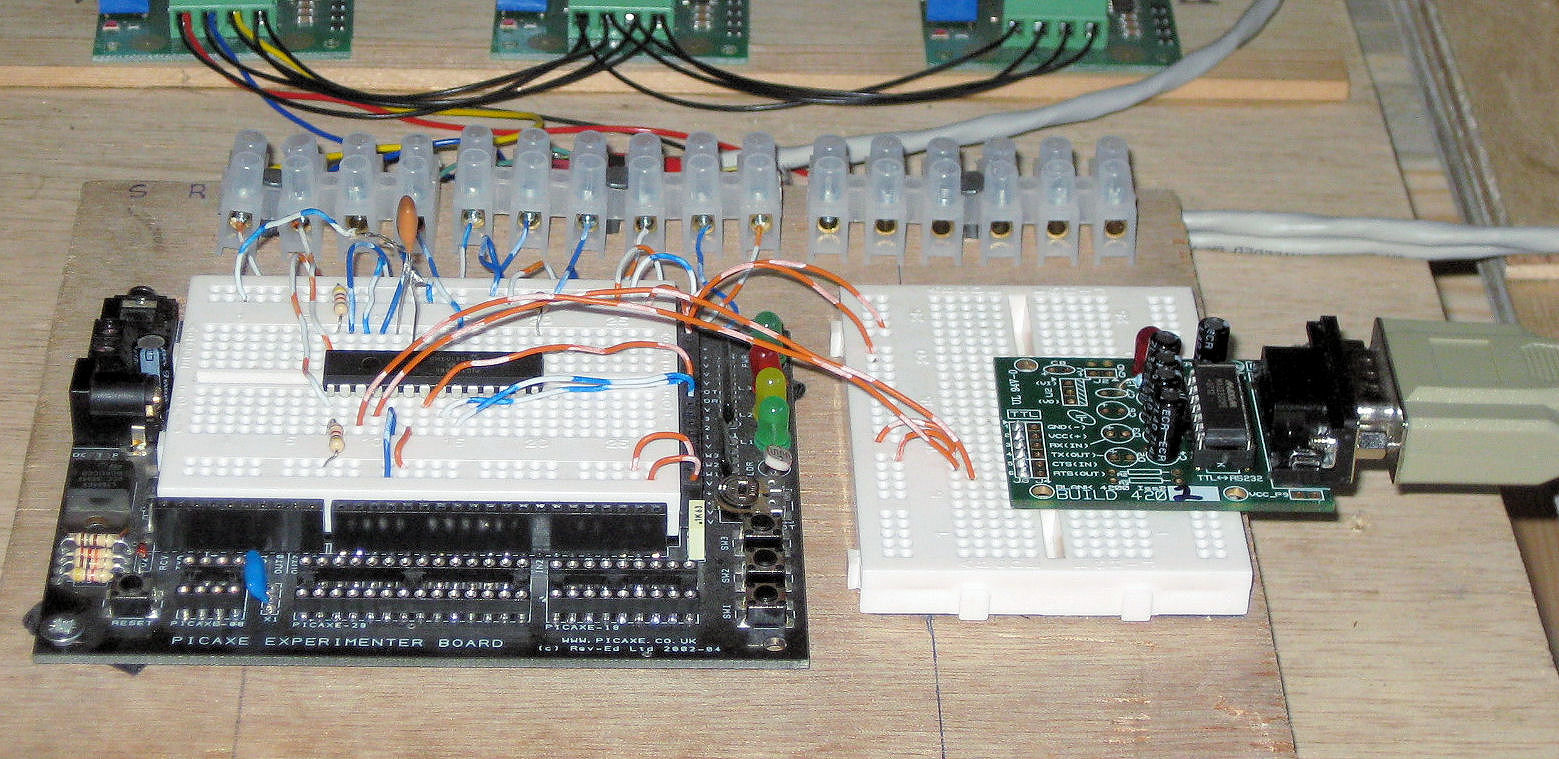
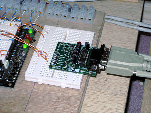
Implementation of the 115200 baud serial
comms requires an additional bit of signal processing
hardware on the SPU. This is because the "hardware" serial-in pin on the 28X1 chip requires true RS232 voltage
polarities at TTL (5V) levels. For serial comms with a PC
this needs either a RS232/TTL Converter Module or a separate
MAX232 converter chip to be incorporated into the data line.
Either approach will work although I've chosen to use
an RS232/TTL
Converter as this is neater for me and also allows a
standard serial cable to be plugged in directly without
having to strip wires etc. The converter module I used has
its TTL connector pins physically inverted and so can be
pressed directly into the breadboard which allows very
simple further connection to the 28X1 chip and the available
5V board supply - see image above.
I've recently come across this
AVITResearch
USB to TTL converter
cable. This has the MAX232 type level shifter circuitry
built into it and can be connected directly to the serial
read and write pins on the PICAXE chip. More expensive than
a MAX232 chip and some capacitors but much less hassle. If
you do use it connect cable blue to 28X1 pin17 (Position
Out) and red to pin 18 (Speed In).
RESULTS
Combined with the MA3 Encoder position
feedback and V2.02 driver and PID software running on a LAN
PC I've found the 115200 baud SPU does improve the quality
of the Mini Motion Platform motion. On my LAN PC I get
refresh times on the PID Servo Controller of around 0.03s
(33 loops/s - see performance tips below) and a smoother
drive. There now seems more scope for adjustment of the PID
control terms and in particular both the Proportional gain
and Derivative term can be strengthened to improve the
higher frequency response for on-ground operations. This
improves touch-down bumps and runway rumble effects.
Generally the in-air motion also seems smoother.
Overall I think it is a worthwhile
enhancement and when the PICAXE 28X2 chip becomes available
the full resolution of the MA3 feedback encoders can be
realised to take the picaxe based SPU to the probable limit
of its capabilities. - UPDATE April '09 - the 28X2
chips have now been released and I've completed work on a
High-Speed
SPU - click on the link.
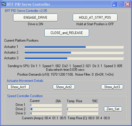
SPEED CONTROLLER CONDITION MONITORING
 The
faster communication speeds available with this enhancement
can be used to add additional capabilities to the system.
One very useful addition is to read real-time current and
temperature data from the MD03 speed controllers and to send
this back to the PID Servo Controller software for display.
This allows you to keep an eye on the real-time loading on
the MD03 speed controllers. You can confirm how heavily
loaded they are generally and can watch out for potentially
damaging current flow or controller temperature rise. This
will be particularly useful during the initial motion
platform setup and commissioning activities when the
patterns of the controller loading might not yet be known.
The
faster communication speeds available with this enhancement
can be used to add additional capabilities to the system.
One very useful addition is to read real-time current and
temperature data from the MD03 speed controllers and to send
this back to the PID Servo Controller software for display.
This allows you to keep an eye on the real-time loading on
the MD03 speed controllers. You can confirm how heavily
loaded they are generally and can watch out for potentially
damaging current flow or controller temperature rise. This
will be particularly useful during the initial motion
platform setup and commissioning activities when the
patterns of the controller loading might not yet be known.
I've put together some additional wiring
diagrams etc for the Enhanced SPU set up and there are also
new chip flash programs to handle the faster serial
communications (I've included a .bas program which adds the
115200 serial comms to the existing SPU without the MA3
encoders - a 16MHz resonator will still be needed).
|
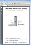
28X1 Pin Designations
(with MA3
Encoders) |
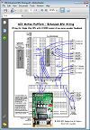
Enhanced SPU Wiring
(with MA3
Encoders) |
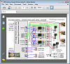
Enhanced SPU
System Wiring |
Enhanced SPU
.bas
Flash Progs
Three versions
are
included - for
normal
potentiometer
feed-
back and for
MA3
encoder
feedback and
a version for
speed
controller
monitoring. |
Note the SPU is built on the
PICAXE Experimenter Kit breadboard (this kit has been
discontinued by PICAXE -
this is the replacement). If you use the AVITResearch
USB to TTL converter
cable then connect cable blue to 28X1 pin17 (Position
Out) and red to pin 18 (Speed In).
PERFORMANCE TIPS
To get the best performance out of this
low-cost drive system there are a few recommendations
worth considering.
-
If possible run the V2 Motion Driver
and SPU Servo Controller on a LAN PC separate from
the main flight sim PC. This will reduce the demand
on the main PC and also give the best fresh speeds from
the motion software. The V2 software is more CPU
demanding and is likely to run faster when not
fighting the flight sim for CPU time.
-
On the LAN PC try setting the process
priority of the Motion Driver slightly lower
than the PID Servo Controller (for example at
BelowNormal) - be very careful however and stand by
the emergency stop button! On my set up the
controller remains stable and runs at a consistently
faster refresh speed, however this may not be the
case on all systems and it will also depend on
the overall demand on the LAN PC - be careful if you
try this.
-
If you do not want the Articulated
Projector drive output from the V2 Motion Driver set
the output mode to NONE in the vis.cfg configuration
file (in the line near the bottom of the file -
change "Pololu" to "NONE"). This will reduce the CPU
demand.
-
Use the Enhanced SPU hardware with
the US Digital MA3 position encoders - this will
improve the quality of the motor control and give
more flexibility in your PID configuration. For the
PID Servo Controller to run at 115200 baud the
PID2.cfg file must be modified - line 28 should be
changed from "9600" to "115200" to set the correct
baud. If you find that line 28 is blank in your
PID2.cfg file then add a new line with "115200"
(without the inverted commas).
-
Move the main supply voltage for the
MD03 motor speed controllers up to 36V - ie use 3 x
12V batteries in series rather than 2. Although the
motors I use are nominally rated at 24V increasing
the voltage supply to 36V has no detrimental effect
on them in my set up. The higher voltage increases
the torque available when the motors are
accelerating or decelerating. Given the short
actuator stroke length it is not likely that the
motors will over-speed, it is the added current flow
and so higher torques that are of interest. If you
try this be sure to monitor carefully the working
temperatures of the motors and the speed controllers
for signs of overheating - a sign of excessive
current flow.
Overall the aim is drive smoothness and I
think the speed enhanced SPU takes us a further step in
the right direction. My
experience is that if the motor drive is slightly rough
then it does not feel right to the pilot in the motion
platform. When some roughness is expected - for example
when on the runway then that's okay but for normal
flight motion you want the platform motion to be a
smooth as you can possibly get it.
© This site is
copyrighted, If you'd like more information or have any
comments please contact me at