IMPORTANT - Ready-Built motion platform drive hardware is now available to buy -
this does away with all the breadboard electronics and
fiddly wiring - see the 64SPU-1 card
page for more details.
April 09 - I've completed work on a
High-Speed SPU based on
the newly released PICAXE 28X2 chip - faster response and
smoother control.
With the motion platforms operational for a while
now I've been able to think through and implement some substantial
improvements and simplifications to the platform control
system. Any way in which the build process can be made
easier and less expensive will make life a bit easier for DIY'ers, and the electrical and control system is a major
part of this. The control hardware has evolved through a
number of variations and is now quite simple and fairly
easily built by competent DIY'ers.
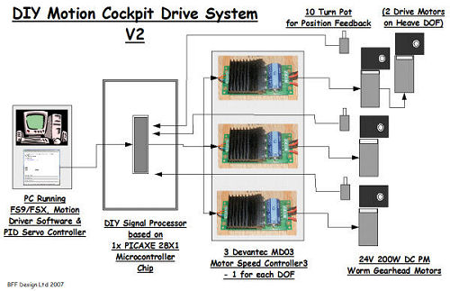
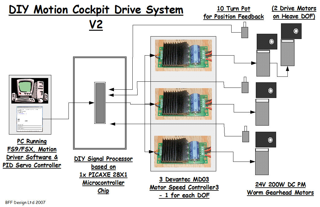
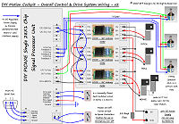
The basic control system is shown above. The
BFF Motion Drive software runs on the sim PC or over a LAN
and generates the platform motion cues. These are shared
with the PID Servo Controller software which runs on the
same PC as the motion driver. The PID Servo Controller
software runs 2-way serial communications with the external
DIY Signal Processor Unit (SPU). The SPU uses a single
PICAXE 28X1 chip to act as a communication device passing
platform position feedback information to the Servo
Controller software and sending calculated motor speed and
direction instructions on to the MD03 motor speed
controllers which in turn drive the electric motors.
The SPU drives the MD03 speed
controllers using the PICAXE chip's
built-in
Philips I2C
capabilities with the single
PICAXE 28X1 chip
as the I2C bus master.
Single Chip Signal
Processor Unit (SPU)
 The SPU uses only a single 28X1 PICAXE
chip. Its role is to collect and write
the platform position feedback information to the PC, and
then to
read back speed demand information and pass it straight
through to the motor speed controllers. It does have
further important jobs - one is the critical role
of detecting loss of signal from the PC. It detects time-outs on the serial data read which allows the SPU to
react almost instantly to any loss of the speed demand
instructions from the PC and to stop the drive to the
platform before any damage is done should the PC or any of
the software hang.
The SPU uses only a single 28X1 PICAXE
chip. Its role is to collect and write
the platform position feedback information to the PC, and
then to
read back speed demand information and pass it straight
through to the motor speed controllers. It does have
further important jobs - one is the critical role
of detecting loss of signal from the PC. It detects time-outs on the serial data read which allows the SPU to
react almost instantly to any loss of the speed demand
instructions from the PC and to stop the drive to the
platform before any damage is done should the PC or any of
the software hang.
 The position feedback send
and speed demand read are done on the same Serial line to
the PC (and with the correct download cable from PICAXE can
be driven from a USB port instead so only a single Serial
or USB port is needed - important, see
note at page bottom). The comms in the basic SPU is at 9600 Baud and is fast
enough to allow overall data refresh rates of 25 sets/sec or
higher. The Enhanced Speed SPU
comms run at 115200 baud which has a significant effect on
the control quality.
The position feedback send
and speed demand read are done on the same Serial line to
the PC (and with the correct download cable from PICAXE can
be driven from a USB port instead so only a single Serial
or USB port is needed - important, see
note at page bottom). The comms in the basic SPU is at 9600 Baud and is fast
enough to allow overall data refresh rates of 25 sets/sec or
higher. The Enhanced Speed SPU
comms run at 115200 baud which has a significant effect on
the control quality.
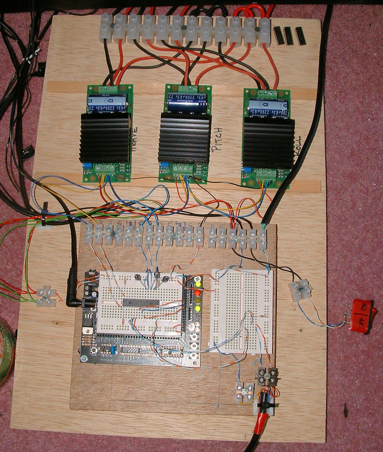
The communication with the speed controllers
makes use of the built-in I2C functions of the
PICAXE chip and of the
MD03 controllers - the wiring is
simple as each controller is linked to the
same two SCL and SDA lines from the SPU - the mode switches
on the MD03's are simply adjusted to give each a separate
"address" on the I2C bus.
There are a number of variations on the
Signal Processor Unit design now available. These cover
different comms speeds and different types of position
feedback devices, they are-
-
BASIC SPU - Uses 28X1 Chip's 8MHz
internal clock, Potentiometer feedback devices and 9600
baud serial comms. Wiring details and diagrams are
below. Option available for 16MHz
clock speed.
-
BASIC SPU + Encoder Feedback - As above
but uses MA3 absolute position encoders for cleaner
position feedback and an external 16MHz clock
(resonator). Details on the
MA3 Encoder page.
-
ENHANCED SPEED SPU - Uses a small amount
of additional hardware to run serial comms at the much
higher 115200 baud. Also needs an external 16MHz
resonator - details on the
Enhanced SPU page.
-
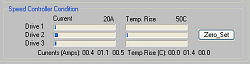
ENHANCED SPEED SPU + Speed Controller
Condition Monitoring - as for the ENHANCED SPU above but
adds real-time speed controller current and temperature
monitoring - requires V2.05 or later of the PID Servo
Controller software. Details on the
Enhanced SPU page.
-
FINALLY, if your don't want to try and
build your own SPU a ready-built signal processor unit
card is available to buy. The
40SPU-1 card uses the PICAXE 28X2 chip and runs at
40KHz - faster than the above options, and has several
additional features. For more details see the
40SPU-1 card page.
PID Servo
Controller Software
The control system is driven by the PID Servo Controller
software that runs on
the same PC as the BFF Motion Driver.
This is where the servo control calculations are done using
the position feedback information from the SPU and the
position demand information from the Motion Driver. As of
April 2009 V2.1 of the PID Servo Controller is available.
 With
system safety in mind the servo controller runs as a separate process
on the PC and communicates with the Motion Driver through a
shared memory area - so any hangs or crashes in the flight sim or Motion Driver will not stop the Servo Controller from
continuing to send control data to the external hardware.
This gives the system two layers of failsafe - one at the
PICAXE chip level which monitors data output from the PC and
the other at the Servo Controller software level which
monitors data output from and the status of the Motion
Driver - both are programmed to cut the drive to the
platform should the data stop flowing.
With
system safety in mind the servo controller runs as a separate process
on the PC and communicates with the Motion Driver through a
shared memory area - so any hangs or crashes in the flight sim or Motion Driver will not stop the Servo Controller from
continuing to send control data to the external hardware.
This gives the system two layers of failsafe - one at the
PICAXE chip level which monitors data output from the PC and
the other at the Servo Controller software level which
monitors data output from and the status of the Motion
Driver - both are programmed to cut the drive to the
platform should the data stop flowing.
This failsafe protection is
necessary. The motor speed controllers act on signals which
request a certain platform speed - not position! The rest of
the control system has to figure out how fast and in what
direction the motors should be running at any moment. If the
control system fails and the speed demand instructions to
the controllers are not constantly updated then the platform
may simply continue to drive at the last requested speed -
straight into the end-stops. The double protection built
into the new design substantially reduces the chance of this
happening.
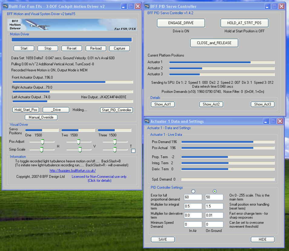
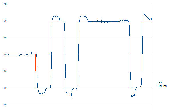
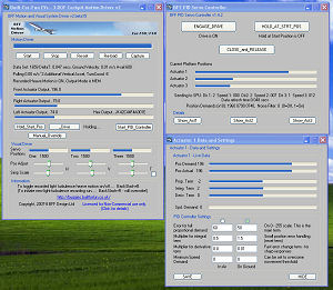
 The BFF PID Servo Controller
is started from the Motion Driver. It uses standard PID control algorithms to determine the required platform
speed to try to get the actual movement to follow the motion described by the Motion
Driver. The settings used for each of the three drive
outputs can be set "live" as the platform is operational so
you can see immediately the effects of your adjustments
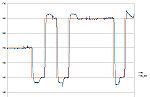
(care required). The
input and output motions can be compared visually, and you
can see the magnitude of the individual PID terms as they
change in real-time. You can also dump a data trace to file
from which all of the variables can be plotted if you wish
to examine your platform response in more detail.
The BFF PID Servo Controller
is started from the Motion Driver. It uses standard PID control algorithms to determine the required platform
speed to try to get the actual movement to follow the motion described by the Motion
Driver. The settings used for each of the three drive
outputs can be set "live" as the platform is operational so
you can see immediately the effects of your adjustments
(care required). The
input and output motions can be compared visually, and you
can see the magnitude of the individual PID terms as they
change in real-time. You can also dump a data trace to file
from which all of the variables can be plotted if you wish
to examine your platform response in more detail.
There is a good article about
PID control
here should you need more detail. In short the final
speed demand for each drive is made up from three elements -
-
the Proportional term is
the main element and sets the speed proportional to the
size of the position error.
-
the Integral term adjusts
the speed based on the accumulating error and is useful
for ensuring the pitch and roll angles return fully to
their upright positions.
-
the Derivative term
adjusts speed on the basis of how fast the error is
changing and can acts as a brake on the system to
reduce overshoot. It can also be used to increase the
controller reaction to sharper position demand changes. This term is the trickiest to work
with as it is most affected by noise in the feedback
signals which can make the response very jumpy. See the
US Digital Encoder support page for how this can be
improved.
The V2 PID Servo Controller allows two sets
of PID settings to be specified for each actuator drive -
one for in-air operations and one for on-ground. This allows
a sharper control response to be specified in the drive
system for runway operations (touchdown bumps, rumble
effects, "off-road"
 excursions
etc) and softer responses for in-flight motions.
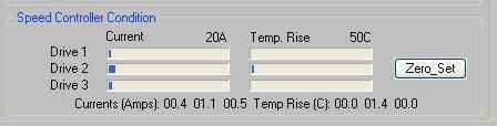
With the
Enhanced SPU the V2.05 software also provides
real-time motor speed controller condition feedback to allow
you to visually monitor the drive system condition.
excursions
etc) and softer responses for in-flight motions.
With the
Enhanced SPU the V2.05 software also provides
real-time motor speed controller condition feedback to allow
you to visually monitor the drive system condition.
For the pilot's benefit the
PID Servo Driver has large start, stop and hold buttons
which allow you to kill the drive quickly should you need
to, and the Tab key remains programmed as a Hot Key to kill
both the Motion Driver and Servo Controller with a single
key stroke should your platform turn into a bucking bronco!
Here's a clip of the software
and SPU in action driving 3 of the DIY linear actuators -
Movie Clip
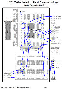
Wiring Diagrams for
the Basic SPU
The Basic SPU wiring details are
available below. The PID Servo
Software is included with V1.5 and later of the BFF Motion
Driver. Details of its use and set up are in the updated
User Manual also included in the software download package. The
manual is also available by itself on the
downloads page. For details
of the Speed Enhanced SPU
design - see here.
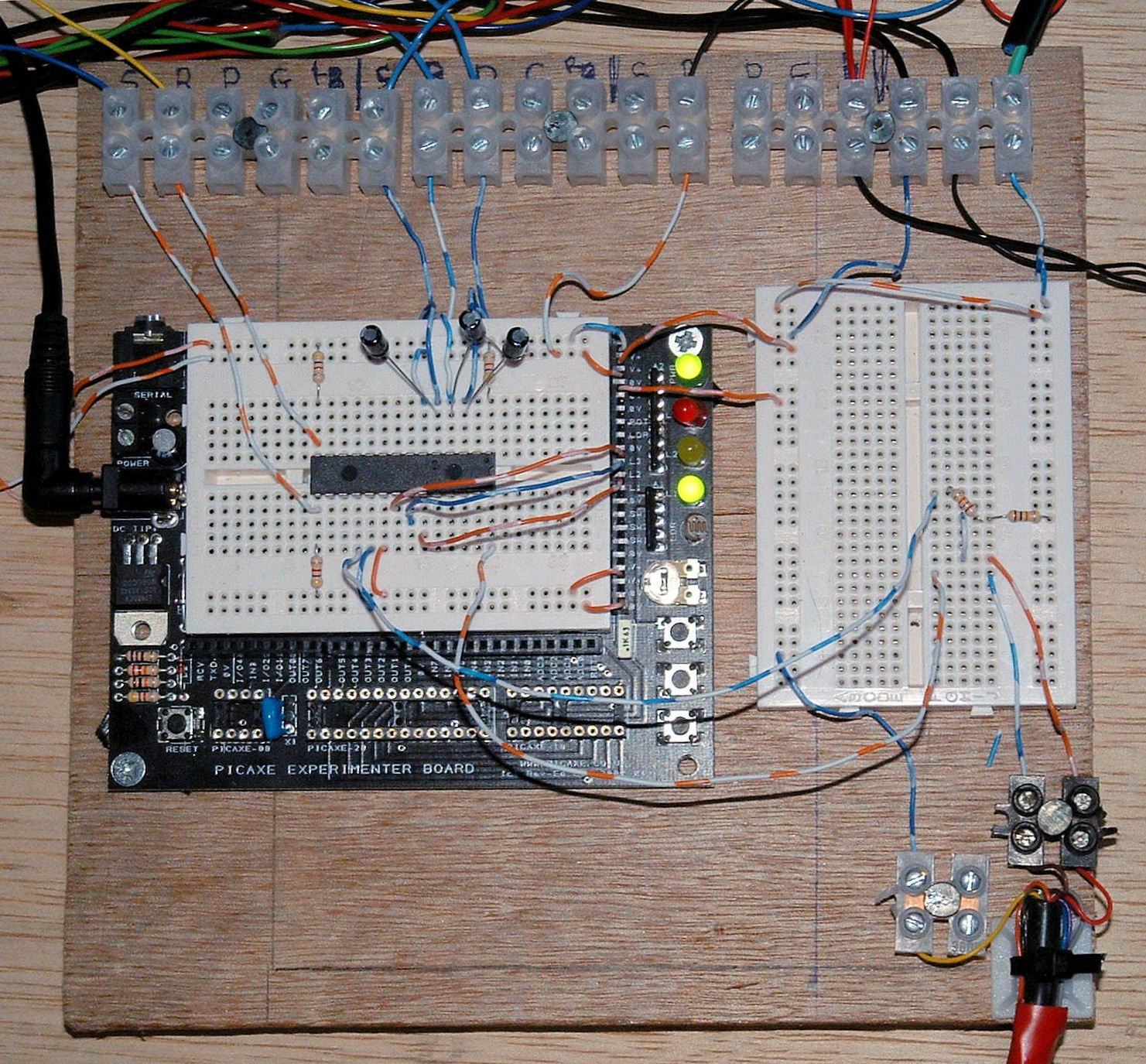
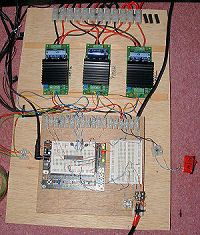
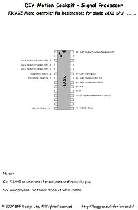
Below - Overall system
wiring, Basic SPU wiring and the 28X1 chip pin designations
.......Note the SPU is built on the
PICAXE Experimenter Kit
breadboard (this kit has been discontinued by PICAXE -
this is the replacement). The 28X1 chip flash program is included in
the motion driver download package.
Have fun ...................
Important Update
Information
If you are using older A.2 firmware PICAXE
28X1 chips then the serial communications require that a
calibfreq statement is included in the flash program to
calibrate the chip frequency. Make sure you are using the
correct .bas flash program (SPU_I2C.bas) and you may have to
experiment with the value used in the calibfreq statement.
If you wish to use the
AXE027 USB cable then I suggest that you alter the
"calibfreq -6" statement in
the flash program to "calibfreq -4" and give it a shot.
ABOVE APPLIES to A.2 Firmware chips only.
August 08 - IMPORTANT The
PICAXE 28X1 chip programming has been updated to allow
28X1 Firmware A.3 chips to be used. Use the SPU_I2C_16.bas program and have an external 16MHz
resonator fitted to the chip if you are using a A.3 firmware
chip. Or, you can use an A.3 28X1 with its internal 8 MHz
resonator if you use the SPU_I2C_8.bas flash program.
Original System Page
Original SPU Design
Original Controllers & Wiring
© This site is
copyrighted, If you'd like more information or have any
comments please contact me at