Previous
Contents
Next
 12. PID Servo Controller 12. PID Servo Controller
12.1
Configuration File Settings
12.2 Operation
12.3 PID Control Settings
12.4 PID Control Settings - Setup Procedures
The BFF
PID Servo Controller and 64SPU-1 hardware
card operate together to form the core of a motion platform
closed loop electric motor servo drive. The software and hardware
support up to three output channels.
The PID
Servo Controller software converts the motion cue output from the
BFF Motion Driver software into motor speed and direction demands
which are used to drive the electric motors via motor speed
controllers. The software will not
operate unless it is connected to an active and properly configured
64SPU-1 signal processor card (or other valid SPU). For full details of the 64SPU-1 read
the
card data sheet.
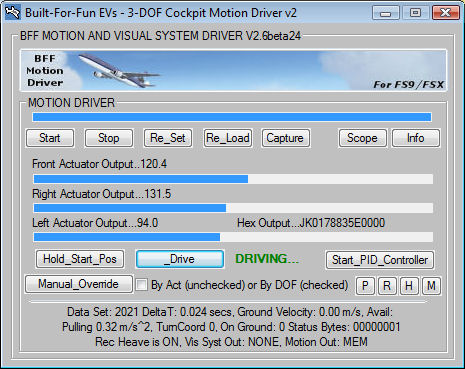
The PID
Servo Controller is installed as part of the motion driver software
package. It is run using the Start_PID_Controller button on
the BFF Motion Driver window.
The
software communicates with the 64SPU-1 hardware using serial comms
via either a physical or virtual COM port. If the PICAXE AXE027
download cable is used speed can be improved by adjusting the
Latency Timer setting for the virtual COM port to 1 ms.
To do this go to Control Panel
- Device Manager and open the COM ports section. Double
click on the AXE027 entry and then select Port Settings -
Advanced and in the BM Options area set the
Latency Timer to 1 ms. You may have to try different
settings to get the best setting for your system.
12.1
Configuration File Settings
Motion
Driver Settings (in .bff config file)
To use the
PID Servo Controller the data output mode of the motion driver must
be set to Mode=MEM. This instructs the motion driver to make
the cue data and other settings available to the PID Servo
Controller through a shared memory area.
The
Port=COM* parameter should be set to specify the com port the PID Servo
Controller should use to communicate with the external 64SPU-1 card.
PID
Servo Controller Settings (in PID26.cfg file)
The
controller software's local settings are held in the PID26.cfg file.
A few settings must be made in the PID26.cfg manually using a
text editor such as NotePad. In normal use the .cfg file does not
need to be accessed manually - the software reads and writes
settings as required.
The
PID26.cfg contents are shown below (comments in blue are NOT present
in the file):
-----------------------------------------------------------------------------------------------------------------------------------------
1. 30
;Start of PID Settings - do not adjust in file
2. 1.0
3. 0.05
4. 0
5. 30
6. 1.0
7. 0.05
8. 0
9. 30
10. 1.0
11. 0.05
12. 0
13. 20
14. 1.0
15. 0.05
16. 0
17. 20
18. 1.0
19. 0.05
20. 0
21. 20
22. 1.0
23. 0.05
24. 0
;End of PID Settings
25. 0
;Feedback noise filter on/off - it is best to use good quality
feedback devices rather than the software filter
26. 0.05
;Noise filer Time Constant
27. 0
;Data trace
28. 115200
;64SPU-1 comms baud rate
29. 00111011
;64SPU-1 bit settings - see 64SPU-1 data sheet Section 3
30. Built-For-Fun EVs - 3-DOF Cockpit Motion
Driver v2
;Title of Motion Driver window
31. I2C
;Data output format identifier
32. COM2
;Dimension Engineering Sabertooth controller comms COM port
33. 38400
;Dimension Engineering Sabertooth controller comms baud rate
34. 128-1
;Sabertooth channel 1 address
35. 128-2
;Sabertooth channel 2 address
36. 129-1
;Sabertooth channel 3 address
37. Normal
;PID Servo Controller Sabertooth comms process priority
38. Yes
;Enable polynomial cue data use
39. Normal
;PID Servo Controller process priority
------------------------------------------------------------------------------------------------------------------------------------------
Lines
10-24 contain the individual PID settings for each channel - these
should not be adjusted in the file. The software reads and writes
these directly.
Lines 24 &
25 define the software noise filtering of the position feedback
data. This is retained as a legacy setting - it is better just to
use good quality feedback devices.
Line 27 is
data trace output setting, =0 for off, =1, 2 or 3 to output data for
numbered channel. Data is written to file PID_Output.txt each data
loop so the output will build up very quickly if left on -
use for short bursts only.
The data items are: Position feedback, Demanded position, Position
error, P, I & D speed demand terms, Total speed demand, Controller
current, controller temp. The data can be inspected and charted in a
spreadsheet application.
Line 28,
the 64SPU-1 baud rate must be left at 115200
Line 29, 8
bit control settings for the 64SPU-1 - see the
64SPU-1 data sheet
Section 3.
Line 30,
motion driver window title - leave as is.
Line 31,
data output mode, = "I2C" for MD03 drive from 64SPU-1, = "SERIAL2"
or "SERIAL2x25" for Sabertooth controller output - see
Sabertooth Quick Start Guide for details.
Lines
32-36, Sabertooth setup settings - see
Sabertooth Quick Start Guide for details.
Line 37,
Sabertooth comms process priority, = Normal, High etc. This can be
used to give the Sabertooth comms process better access to system
resources if it is running on the same sim PC as the flight sim and
is struggling to produce smooth output.
Line 38,
best to leave as is - this enables the servo controller to use
position demands sent from the motion driver as polynomial curve
fits. This gives smoother interpolation and smoother D term
behaviour.
12.2 Operation
 The
PID Servo Controller will only run properly once your 64SPU-1 card
has been connected and configured. See the
64SPU-1 data sheet
for details for the card setup. The
PID Servo Controller will only run properly once your 64SPU-1 card
has been connected and configured. See the
64SPU-1 data sheet
for details for the card setup.
To run the
PID Servo Controller start the BFF Motion Driver and once it is
running and in Hold mode select the Start_PID_Controller
button.
The PID
Servo Controller will start and try to communicate with the 64SPU-1
card - check the messages in the text area of the window. If the
comms are established successfully the software will report the
current actuator positions, servo loop refresh speed etc. The
64SPU-1 LEDs will also change to running status if the comms are
operational - see the
64SPU-1 data sheet for details.
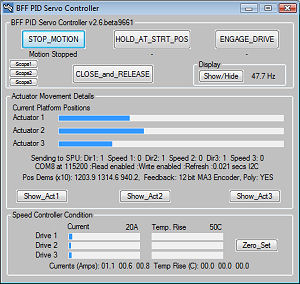
PLATFORM START PROCEDURE
1. With
Motion Driver on Hold, select servo controller
HOLD_AT_STRT_POS - to move the platform to its park/hold
position.
2. Select
ENGAGE_DRIVE to make the servo drive active for cue
following.
3. Now use
the Hold_Start_Pos and Drive buttons on the motion
driver to move the platform smoothly between Hold and Drive modes as
required.
PLATFORM STOP PROCEDURE
1. With
the servo drive still engaged use the motion driver Hold
button to move the platform smoothly to park/hold position.
2. Select
the servo controller HOLD_AT_STRT_POS to fix the platform at
park/hold position, and when required select STOP_MOTION to
stop the drive.
In
STOP_MOTION mode the servo drive will request zero speed from
the motors. When CLOSE_and_RELEASE is selected the software
stops sending speed demands and closes. Note that the motor speed
controllers may not release the zero speed demand on the speed
controllers until they are powered-down.
The
Show/Hide button is used to minimise the display - this reduces
CPU load and lifts refresh speed slightly.
Scope*
buttons to show/hide the built-in oscilloscope for the chosen
channel.
The Speed
Controller Condition area shows live feedback of MD03 motor
controller current and temperature. It is only active if MD03's are
present and readback is enabled in the PID26.cfg file. The values
are relative - use the Zero_Set button to zero them at
startup. They provide a useful visual monitor of controller
condition.
12.3 PID Control Settings
The
Show_Act* buttons are used to display the control details for
each channel and to set the PID control parameters.
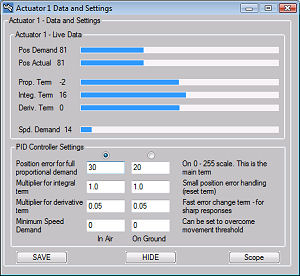 The
individual components of the speed demand output are displayed in
the upper window area. In the lower area the PID settings are shown. The
individual components of the speed demand output are displayed in
the upper window area. In the lower area the PID settings are shown.
There are
two sets of PID settings - one for in-air operations and one for
on-ground operations.
WARNING - changing the PID settings can
make the drive unstable - take great care when making changes and do
so by making small adjustments only. DO NOT make changes to the
settings whilst the platform is in motion, stop the motion first
using the HOLD and STOP buttons. Test changes by first
using the HOLD_AT_START_POS button to instruct the system to
hold position before moving on to full drive with the new settings.
Position Error for full proportional
demand
The
position error that gives full speed demand. If the instantaneous
error is below this value the speed demand is scaled down if it is
above this value the speed demand holds at maximum. The smaller the
value is the faster the platform movement will respond to changes in
the demanded position. However the smaller values will also mean it
has more trouble slowing to a stop once the rig has moved to the
demanded position. So small values give fast response with likely
position overshoot, and large values give slow smooth response with
no overshoot.
Values between 20 and 100 as a guide
only - set with reference to the specified feedback range for the
actuator.
Multiplier for Integral Term
Also know as the re-set term, this calculates a
contribution to the speed demand based on how long a position error
is sustained. It is mainly of use for making sure that the position
comes back to that demanded when the proportional term has lost its
effect on small position changes.
Guide values would be from 0 to 4 or 5.
Multiplier for
Derivative Term
The trickiest term to get right. This speed demand
component is calculated from the rate at which the error is
changing. If the rate is high it means that the actual and demanded
positions are either moving apart quickly or coming together
quickly. If they are moving apart quickly the rig isn't moving fast
enough and the D term gives a boost to the speed, if they are coming
together quickly the rig needs to slow down faster and the D term
acts as a brake on the motion. The practical effect can be as a
brake and to help to reduce the extent of any overshoot there may be
if the proportional term is set to respond strongly to position
errors. Its use is therefore likely to be able to allow faster
response Proportional terms to be used by reducing the extent of the
associated overshoot. It can also be used simply to enhance the
response to events such as touch-down bumps when a slow proportional
response is being used.
Guide values would be from 0.01 to 0.2 - depends
strongly on feedback resolution and quality, use 12bit feedback from
the 12ADC-1 card for best effects.
Minimum Speed Demand
This is an additional term which
allows a small fixed speed demand to be added in to the total to
help overcome any friction based movement threshold in the system.
Setting this just below the speed demand that actually initiates
movement may help improve the speed of response.
Guide values, 0 to 20.
12.4 PID Control Settings -
Setup Procedures
Unfortunately there is no set of
settings that will be correct for every motion platform. Many of the
above variables need to be set experimentally. Start by setting the
Integral and Derivative terms to zero and work with the Proportional
term first. This should be set at the higher end of the guide scale
and then reduced gradually until the rig motion in response to step
position inputs starts to overshoot or oscillate.
If you wish to make use of the
Minimum Speed Demand setting, set this next. With the Servo
Controller holding mid position increase the setting from zero until
the movement starts to oscillate slightly – do it in small steps. A
setting which holds the motion steady but just “ready” to move is
what you are looking for. If this is set too high you will feel a
“clunk” each time the platform drive changes direction.
The Integral term can also be set
with the controller holding position. Increase the values in small
steps until you start to see small oscillations occurring. Watch the
progress bars – you will see the integral term building until a
small movement adjustment takes place and the term reduces again.
The Derivative term will be the
hardest to get right. If you feel it is not needed then don't use it
– set it to zero. Again increase the setting in small steps from
zero and watch the response of the rig before going on to see if you
can then further reduce the Proportional term error setting. You
will see the D term progress bar start to jitter as the D term is
increased, this will give an indication of the limit of
applicability with your feedback quality.
ALWAYS
TAKE CARE – ADJUSTING THE CONTROL SETTINGS CAN CAUSE RAPID MOVEMENT
OF THE PLATFORM. ENSURE SAFETY PRECAUTIONS ARE TAKEN AND ENSURE THE
PLATFORM TRAVEL LIMIT SWITCHES AND ACCESSIBLE EMERGENCY STOP BUTTON
ARE FITTED AND FULLY OPERATIONAL.
Previous
Contents
Next
|