12ADC-1 ADC Card - for higher
resolution position feedback
In the motion platform servo drives described
on the site standard potentiometer position feedback to the
64SPU-1 signal processor card is
at 10 bit resolution - 1 in 1024.
12 bit (1 in 4096)
MA3 absolute position encoders
provide a significant improvement in the position feedback
resolution for the DIY motion platform drives and provide
smoother motion control. They are however a bit expensive
and can only be purchased directly from the US based
manufacturer US Digital.
The new 12ADC-1 card is a 12 bit resolution
analogue to digital converter card that can be used with the
64SPU-1 signal processor card to increase the resolution of
your motion platform position feedback - without the cost of
MA3 encoders. It can be used with standard precision
potentiometers to provide a level of position reporting very
similar to that of the MA3 absolute encoders and, when used
with the 64SPU-1 card, at a faster refresh rate.
The 12ADC-1 uses the
Microchip Technology MCP3204 ADC chip to provide 12bit
conversions for up to 4 input channels - although only three
channels are used in the 12ADC-1 default programming for 3
DOF motion drives. The MCP3204 chip is interfaced using an
on-board PICAXE 20X2 64MHz microcontroller which is
programmed to export the 12bit position conversions via a
single wire serial data connection to the 64SPU-1. The card
can export smoothed 12bit conversions for 3 channels at
approximately 70 Hz and can lift the 64SPU-1 servo loop
refresh speed to the same rate. Each data set at 70Hz is the
sum of 5 analogue to digital conversions for each channel to
produce the smoothed output.
The 12ADC-1 is easy to wire - see the
datasheet
for details.
PERFORMANCE
|

12ADC-1 Comparative
Performance |
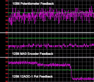
The relative
performance of the 12ADC-1 is illustrated in the image left
(click to open in a new tab).
The purple traces
show sample position feedbacks to the 64SPU-1 for standard
10bit potentiometer, 12bit MA3 encoder and 12bit 12ADC-1 pot
feedback. The traces are highly zoomed to make the noise
levels visible - each trace has a vertical division of 0.1
parts in a scale of 255.
You can see the
improvement in both 12bit feedback methods over the top
10bit pot feedback. Also clear is the similarity between the
two lower traces showing the 12bit MA3 encoder and 12bit
ADC-1 pot feedback. Note that the larger steps in the bottom
trace are due to the platform changing position slightly.
The 12ADC-1 was
connected to a Vishay Spectrol
533 precision potentiometer using shielded grounded
cable. Care was taken to electrically isolate the pot shaft
and body from the drive electric motor to prevent noise
transmission to the feedback line.
AVAILABILITY
The 12ADC-1 card
is available to buy now - follow the link to the
order page.
64SPU-1 firmware B
programming will be required to enable the 12ADC-1 card to
be used with the 64SPU-1. Owners of firmware A 64SPU-1
cards (ie cards ordered prior to 8/8/2010) will need to re-program their cards with firmware
B - please email me for the firmware B flash program and
instructions.
HARDWARE
DEVELOPERS
The PICAXE 20X2 chip
used on the 12ADC-1 card to interface with the MCP3204 ADC
chip is socket mounted and can be removed from the card for
reprogramming. Options for reprogramming could be to
increase or reduce the number of ADC channels, change the
sampling for faster refresh rates, change the serial output
baud or format or to add two-way comms to implement
"conversion on request" functionality etc.
For assistance to
programmers the
default .bas programming is available on request to
customers to illustrate the core MCP3204 SPI interface
coding and data output options.
 This
capability will mainly be of interest to developers familiar
with PICAXE microcontroller programming. For readers who are
not it is probably worth explaining that PICAXE
microcontrollers are easy to program
using a BASIC type language and
free programming software provided by the supplier.
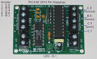
The mapping between the 20X2 pins and the
12ADC-1 output connections and 5 pin header are shown on the
image right. The 20X2 hardware serial input and output pins
and pwm output pin are mapped to the main digital output
connector on the 12ADC-1. The hardware serial pins can be
configured to run with either normal or inverted TTL level
serial comms at high baud rates. The 5 pin header provides
options for programmed jumper settings.
© This site is
copyrighted, If you'd like more information or have any
comments please contact me at