Sim Project Links

EV & other Stuff


Component Info

Electric Motors

Speed Controllers

Batteries

Adhesives

Ball & Sockets Joints

Bearings

Gears

Chains & Sprockets

Shaft Collars

Shaft Steel


Component Search

Component Information

Order Pages

Contact

Conditions

DIY Force Feedback Flight Yoke

DIY Force Feedback (Control Loader) Flight Yoke

BFF Yoke  FFB

Alternative - OpenBeam Yoke

BFF Yoke  FFB

Project Gallery

Heavy jet control applications

Aersim 747 Simulator

Related Project

BFF Motorised Trim Wheel

Motorised Trim Wheel

NOTE: The documentation listed on this page is for the DIY FFB yoke project. HOWEVER the system setup, wiring and software documentation is also relevant for design and build of Control Loader systems in general. Please contact me for guidance.


Force Feedback Flight Yoke

DIY FFB Flight Yoke

Some movie clips of the test rig are on Page 2

BFF Yoke  FFB

Check out the OpenBeam yoke for an alternative build..

The home-build project described below is a force feedback flight yoke that can be used with MS FS9/X and X-Plane flight sims. The FFB yoke provides variable control feel generated by electric motors built into the flight controls. This makes the flight yoke feel much more realistic - its forces and vibrations vary with the varying phases of the flight and ground operations.....


It is an advanced level project and requires good mechanical and electrical build skills. This is a project for the flight sim enthusiast; as a working estimate the project will cost about UKŁ800 (+ control wheel) to complete (depending on motor, encoder and other component prices.


The project follows the same pattern as other flight sim projects on the site - you will find detailed plans, essential software and key bits of electronics below. Obtaining the other parts and materials needed for the project is up to you.


The main elements of the project are:


Yoke Mechanical Construction

DIY Force Feeback Flight Yoke

Electrical & Control System

Brushless Motor Driver

Control Loading Software

PROJECT DOCUMENTATION

DIY Yoke - Mechanical Plans


1.
Yoke Mechanical Plans (password is: yoke - updated 29/9/11)


   (Also check out the OpenBeam yoke as an alternative construction approach....)


CL System Overall Setup and Commissioning - UPDATED for new CL_SPU_USB & BLDRV3 driver cards


2. README FIRST PLEASE - Project Set up and Commissioning Steps (Nov 18)


   For details of Automatic Power-up Calibration (APUC) feature a separate APUC document is available here.

CL Driver Cards and System wiring - UPDATED for the new CL_SPU_USB & BLDRV3 driver cards


3. CL_SPU_USB + BLDRV3 Card Datasheet (Nov 18)

4. System Wiring

5. Wiring Notes

6. Power wiring & Grounding Detail

7. Driver card dimensioned drawing

7b. Motor Wiring Diagram - 60ST & 80ST Servo Motors


CL System Software

9. CL Software Download (updated 4/21)

10. CL Software Online User Guide

11. CL Software Revision History


PLEASE read the above documentation carefully if you are interested in building the DIY CL Yoke or your own flight controls using the CL system.


The force response of the yoke varies with flight conditions so that changes in airspeed, trim settings etc cause the feel of the controls to change - similar to the behaviour of real aircraft controls.... This makes for force feel much more like real flight controls.

The force levels produced are also much higher than on conventional FFB joysticks. The default system set up will produce single handed aileron control forces up to 4.25 kgf (~9 lbf) and elevator forces up to 9 kgf (~20 lbf).

Larger forces can be generated but would require the transmission ratios to be increased.

The yoke's range of travel is +/- 90 Deg on the aileron axis and 155 mm on the elevator axis.

Brushless Motor Driver

NEW CL_SPU_USB + BLDRV3 Drivers

BFF CL Software

The force components generated by the control loader system include:

  • Airspeed dependent aerodynamic loading (centring forces proportional to control surface displacement and airspeed)

  • Adjustable aerodynamic force gains (equivalent to adjustable control surface area)

  • Angle of attack (alpha and beta) effects (eg for longitudinal stability response)

  • More realistic trim behaviour (independent of simulator trim system, controls can be force trimmed in any position)

  • Control surface static & dynamic weight effects (aircraft acceleration effects)

  • Prop-wash effects

  • Engine vibrations (vary with power & rpm)

  • Runway vibration effects (vary with runway speed)

  • Stall buffeting effects (frequency and amplitude definable - eg stick vibration type behaviour)

  • Damping and friction adjustments (-ve gains definable)

  • Auto Pilot following

Note that the plans do not include the control wheel (yoke) - choice of which is likely to be a matter of personal preference or dictated by the particular cockpit build. The plans show a 25mm outside diameter hollow tube to which you must secure your wheel. Please make sure your choice of wheel is strong enough to carry the forces (some plastic yokes designed for light spring loading may struggle with the force levels).

FFB Yoke Mechanical Build

Force Feedback Flight Yoke

Yoke Construction

The mechanical build is described in the pdf plan set available below. The plans cover component detailed dimensions, bought component details, and build/assembly procedures. The design has an unenclosed mechanism and is primarily intended to be built into a flight cockpit. For desktop-use you should provide covers for the mechanism.

The pdf document is password protected - the password is: yoke

DIY FFB Flight Yoke Plans

DIY FFB Flight Yoke Plans

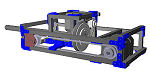
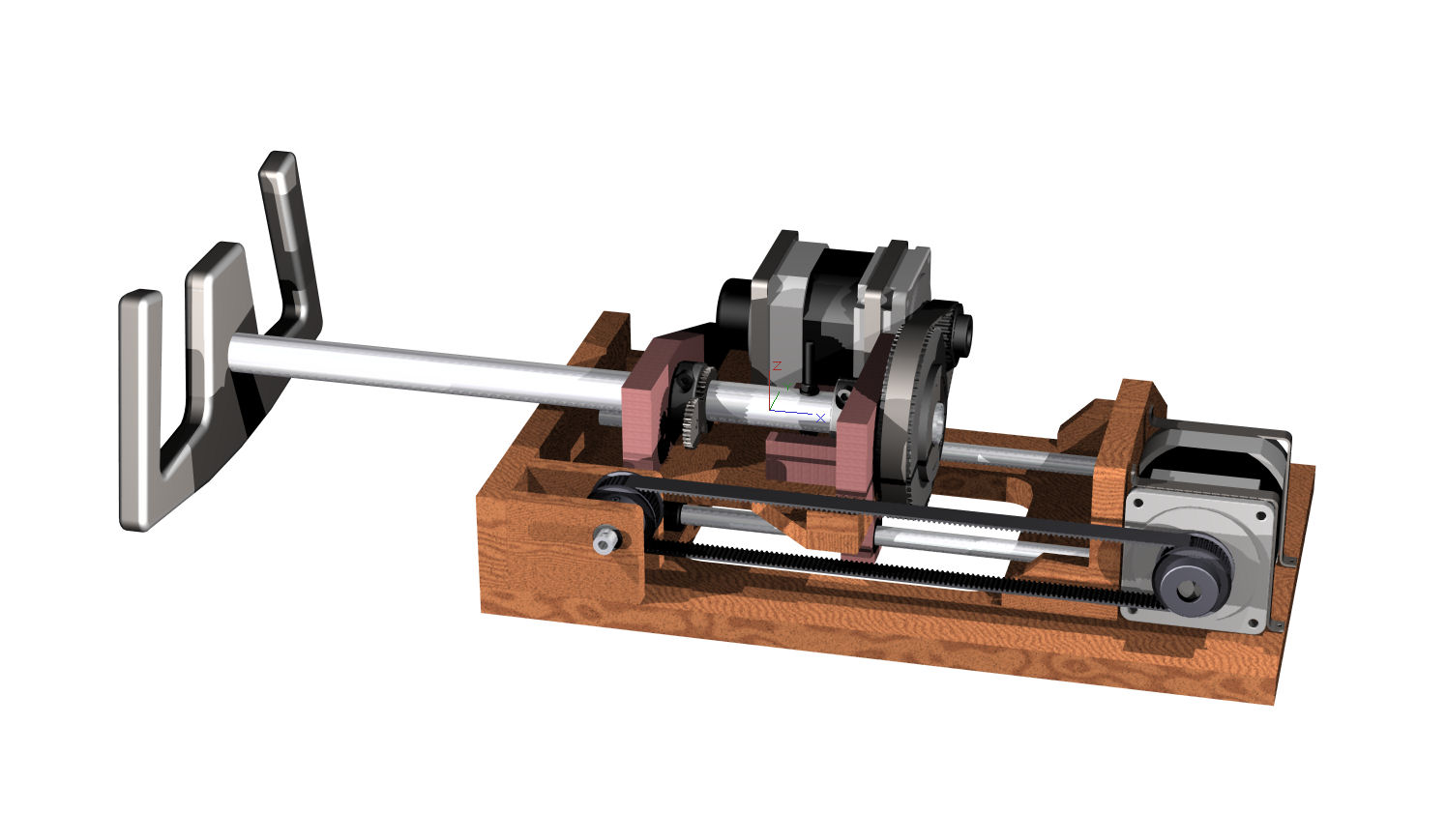
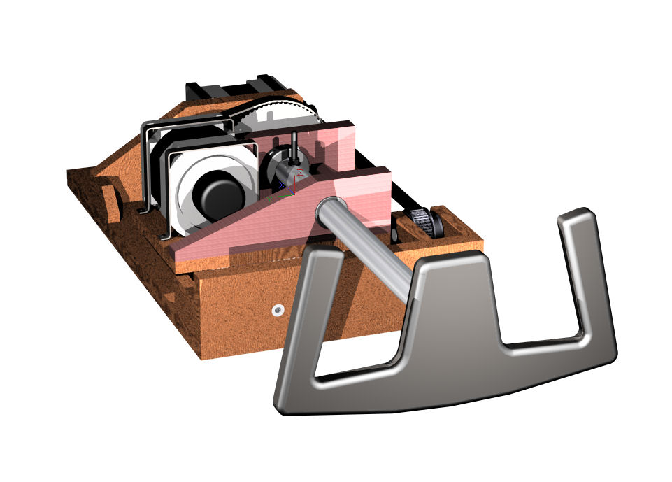
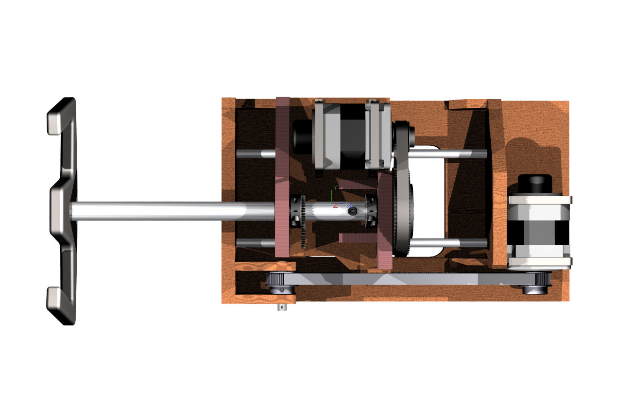
The yoke construction is fairly simple in principal - but needs to be built accurately. The aileron drive motor, wheel tube and control wheel (not included) are mounted on a travelling carriage, which itself is mounted on low friction linear guides and linear ball bushings. The control wheel tube is mounted in needle roller bearings on the carriage. The carriage is driven by the elevator motor via a toothed belt loop. The elevator motor is mounted on the base structure of the yoke at the rear.

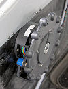
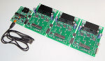
Each movement axis is loaded by a single 3 phase BLDC motor (fitted with 360 cpr quadrature encoder). The motors are specified in the drawings. An important characteristic is their sinusoidal back EMF which enables very smooth response to the sinusoidal commutation voltages from the purpose designed BFF BLDRV3 drivers.
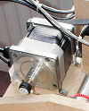
DIY Force Feeback Flight Yoke - BLDC Motor

BLDC motors - used

with specialised controllers..

The BLDC motors are sized to allow simple toothed belt torque transmissions to be used whilst still providing good levels of force output. These belt drives are easier to build than spur gearing and are fairly tolerant of slight misalignments and positioning errors likely to be found in DIY constructions.

The force levels are such that at the higher levels one handed operation of the yoke becomes quite uncomfortable quite quickly if the control is displaced or untrimmed. The yoke needs to be secured to a fixed base otherwise it will move under the generated loading. At full load with 24V supply the elevator loading is about 9 kgf (20 lbs), one handed aileron operation at full load requires about 4.25 kgf (9 lbs). These forces are typically with the controls fully displaced during a flight manoeuvre, force levels during normal flying conditions are much lower than this off course.

Provision is made for fitting potentiometers to report the control position.

NOTE the plans do NOT include details of the control wheel - builders must source their own. The hollow yoke tube shown in the design is 25mm outside diameter. Wiring for any buttons on the wheel can be routed through the yoke tube.


A number of videos clips of the prototype in operation are on Page 2.


MOVIE CLIPS ON PAGE 2


Drawing Set Revision History


29/9/11 - Sheet S001-2 raised to R2 - corrected item 2 (front plate) width.

19/9/11 - Sheet A004-1 raised to R2 - corrected item 24 (belt) length.


© This site is copyrighted, If you'd like more information or have any comments please contact me at


Copyright © 2011-21 BFF Design Ltd All Rights Reserved.