DIY
OpenBeam FFB Flight Yoke
UPDATE Nov '18 - 3D Printing stl
files now added for adaptor parts to allow 60ST-M01330
motors to be used in the yoke.
UPDATE Jan '17 - More
detailed plans now added here.
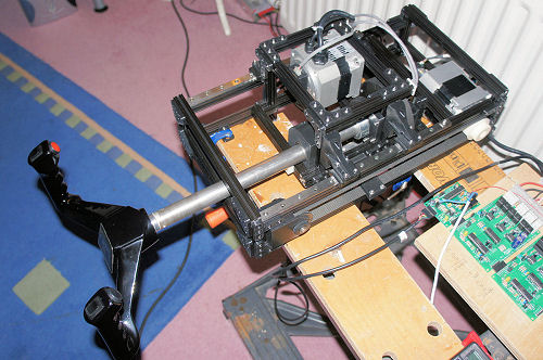
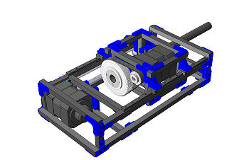
This force feedback flight yoke provides an alternative build
approach to the original timber
structure CL yoke shown here. It will be of interest to
builders who do not want or aren't able to get into making individual
components from timber or metal.
The yoke's framework is assembled from
OpenBeam
aluminium extrusions, with other brackets and components
3D printed.
|
DIY CL Yoke - constructed from OpenBeam beams
and 3D printed parts |
The drive motors and transmission
specifications are more or less the same as for the timber
yoke, as is the force performance.
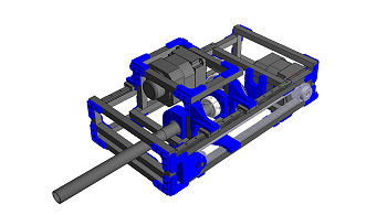
Like the original timber version, this OpenBeam
FFB yoke is designed to be installed behind the sim
instrument panel; it is not intended as a desktop device.
The OpenBeam system offers a flexible way of
building structures but I was initially concerned that the 15mm
square OpenBeam extrusions might not be rigid enough to deal
with the forces developed by the drive motors. However the
framework
has proved surprisingly rigid on its own, and when secured
to a solid support structure it is perfectly adequate for
operation - the control wheel feels solid in use.
|
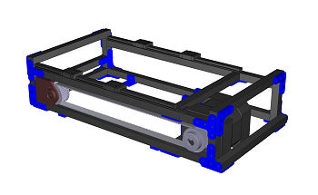
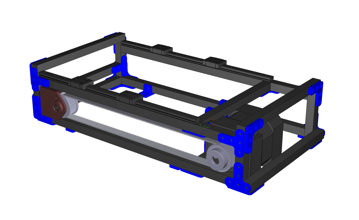
Base - Frame with elevator axis drive and linear
guides for supporting the moving carriage |
The 3D printed components - belt pulleys,
bearing housings and various brackets have also proved
effective. Their strength and accuracy depends off course on
material and printer choices. I use a Zortrax M200 printer
and have produced the components using the Z-Ultrax
material.
Base:
The base frame provides the support structure
for the elevator axis drive motor and belt transmission, and
the linear guides on which the upper moving carriage slides. It
also provides the mechanical end stops for the elevator
movement.
The design uses linear guides
with roller ball carriages rather than the round rails with
linear bearings used in the original yoke.
|
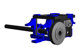
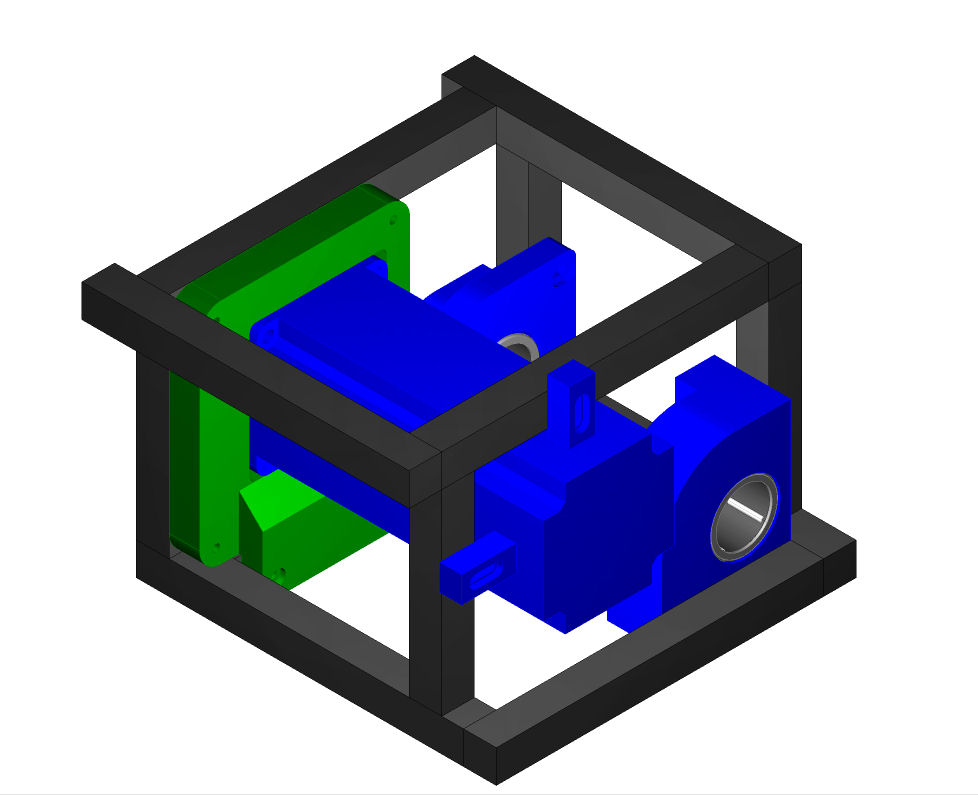
Carriage - slides on the base frame guides and
carries the aileron axis drive. |
The elevator drive is the same as for the
original yoke - a 3mm pitch toothed belt driven by the
brushless motor at the rear and with an idler pulley at the
front. The idler pulley is supported in a 3D printed housing
which can be position adjusted to provide belt tensioning.
Carriage:
The moving carriage sits on the linear guide
rails on the Base to provide the elevator axis movement. It
carries the Aileron axis drive motor and single belt stage
which rotates the yoke tube. The yoke tube is supported in
needle roller bearings housed in 3D printed bearing
housings. The front bearing housing also provides the
aileron axis mechanical end stops.
|
DIY CL Yoke - constructed from OpenBeam beams
and 3D printed parts |
Care needs to be taken on assembly of the Carriage on the
linear guides - the guide rail fixing screws should be left
loose during assembly to ensure that the rails find their
true parallel positions when the carriage is mounted. They
are then tightened once the carriage is secured and so allow
smooth fore/aft movement for the elevator axis.
The resulting movements in both the elevator and aileron
axis are very smooth, and the loading from the brushless
drive motors and BFF CL cards is as smooth as expected
from the BFF CL system.
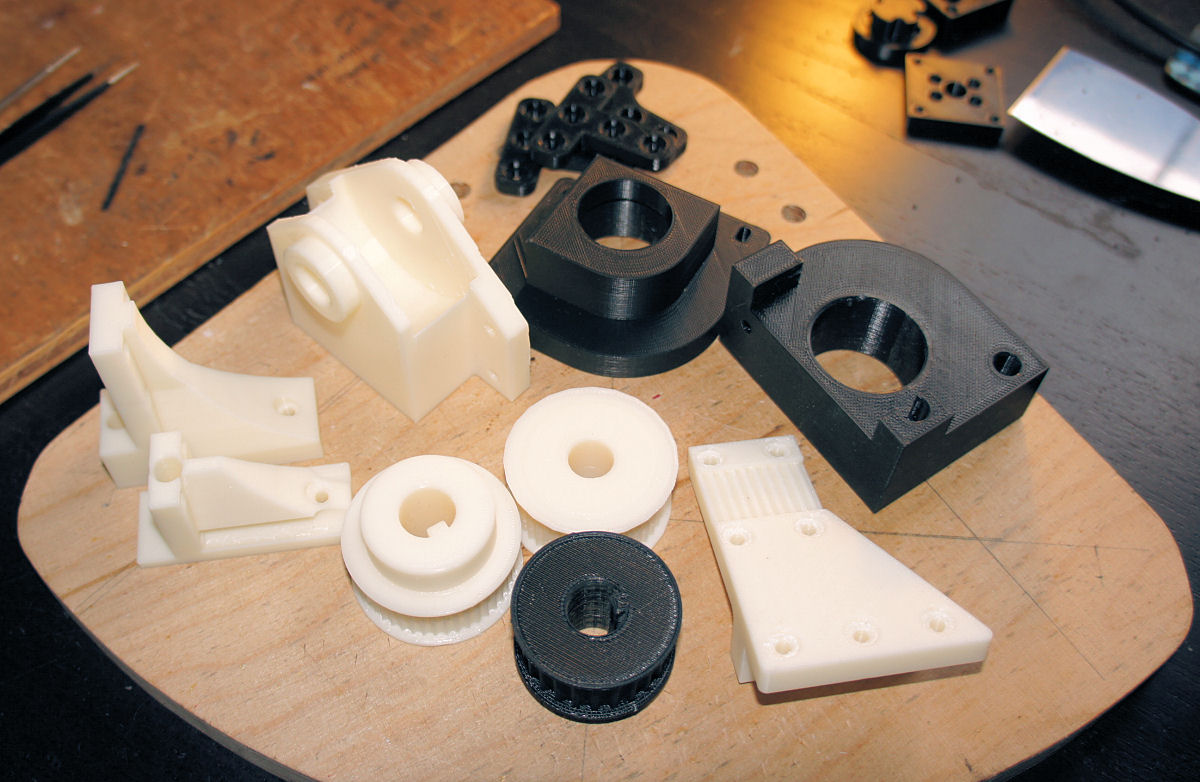
3D Printed Components:
|
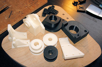
3D Printed parts - including belt pulleys and
bearing housings |
Most of the components in the build aside from the OpenBeam
aluminium beams and bought transmission components
(bearings, belts) are 3D printed. The printed parts are:
-
L and T brackets to secure the beam sections together
-
Mounting feet
-
Yoke tube bearing housings
-
Linear rail fixing brackets (to secure the main carriage
to the linear guides)
-
Elevator axis belt attachment bracket (to connect the
belt to the moving carriage)
-
Drive and idler toothed belt pulleys
-
Idler pulley housing
-
Rear end stop for carriage
The quality of the 3D printing needs to be good for several
of the components. The bearing housings need dimensionally
accurate holes to accept and hold the bearings and the
toothed belt pulleys need accuracy to reproduce the tooth
forms fully and to produce the shaft mounting holes to the
required fit.
I use a Zortrax M200 printer and have used their
Z-Ultrax
material to good effect. I have found that some shrinkage
allowance on holes is required to ensure accuracy for
bearing and shaft fits. On the belt pulley shaft holes about
0.15mm oversize allowance is needed to end with a firm press
fit of the pulley onto the motor shaft. On the larger
bearing housings about 0.2mm allowance is required.
One particular advantage with the belt pulleys is that an
integral key can be included in the printed pulley shaft
hole which makes fitting the pulley much more
straightforward than before.
There's a fair bit of printing time involved, but if you
have access to a 3D printer it should still work out fairly
inexpensive in terms of filament cost.
Movie Clips:
Here's a YouTube clip of the yoke....
Drawings and Specifications:
UPDATE Nov '18
To use 60ST-M01330 servo motors in the yoke,
flange adaptors and a few other parts are required.
60ST Motor
Adaptors STL Files
NOTE: To use the 60ST motor, the drive
belt on the aileron axis must also be changed from the
450-5M-15 shown in the buy-list to the shorter 425-5M-15.
The adaptor places the motor centreline slightly closer to
the yoke tube and so a shorter belt is required.
UPDATE 13/1/17
I've updated the yoke plans pdf - it now
includes the build sequence and more details of the
components. Click on the image for the pdf.
I hope also to be able to offer the full set
of 3D printed parts for sale.
UPDATE 18/1/17 Buy List and .stl files
for 3DP printed components now available, see links below -
Buy_List.pdf
3D Printing
STL files
IMPORTANT: To work well the 3D
printed parts must be of good quality (dimensionally
accurate and with reasonable strength). This implies a
reasonably dense fill and good internal bonding. The belt
pulleys and bearing housings especially need good
dimensional accuracy on internal diameters used for shaft or
bearing location. You may need to experiment with these to
determine what if any adjustments are needed with your
printer and material to get internal hole diameters to give
a firm press fit of the pulleys on motor shafts, and of
bearing into housings.
For reference on the pulleys I increase the
hole diameter by 0.18mm on my Zortrax to get a good press
fit of the pulley on the motor shaft. The bearing housing
stl models already have a 0.15mm increase in dia on the
bearing housing holes to get a firm press fit of the bearing
into the housing.
I hope also to be able to offer the full set
of 3D printed parts for sale soon. Please contact me for
more information if you would like a set....
So more to follow - I'll add further details as
I get them ready....
© This site is
copyrighted, If you'd like more information or have any
comments please contact me at