UPDATE Oct 2011 - The DIY Linear
Actuator plans are now also available as part of the
Full Download Plans Set
available from the plans order page. Previously they were
only available bundled with motion software orders.
(For some movie clips and pictures of the actuators
fitted to a motion platform check the Platform 2 pages
here. NOTE - v2 of the
actuator plans now released.)
Linear
(push/pull) actuators are a common means of drive for
commercial motion platforms. Their use in DIY systems seems
less frequent, although there are a few examples around
which utilize trapezoidal type lead screws as their primary
drive transmission elements. The preferred drive method for
electrical actuators is by ball screw which offers better
speed performance and overall efficiency but have the
unfortunate characteristic (at least for most DIY'ers) of
being horribly expensive.
Lead/ball
screw drives are not the only means available for linear
actuation however, industrial equipment routinely uses both
roller chain and toothed belt type transmissions for
generating linear movement and packaged actuators are
available that use these methods. These don't match ball
screw performance in some applications but for those of us
interested in a low-cost alternative which may be useful in
DIY motion platform design they are worth looking at.
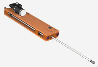
 I've
had a go at designing an electrically powered linear
actuator which uses a standard roller chain drive. Looking
at the design it would be possible to do a ball-screw
version but this would at least double the cost of the parts
- including the drive motor, the cost of parts for my roller
chain prototype was about ŁUK150. It has a 24V 200W drive
motor, stroke length of 425mm, max speed of 390-450 mm/s
(load dependent) and a theoretical static rod thrust of 50
kgf at the motor's rated torque output.
I've
had a go at designing an electrically powered linear
actuator which uses a standard roller chain drive. Looking
at the design it would be possible to do a ball-screw
version but this would at least double the cost of the parts
- including the drive motor, the cost of parts for my roller
chain prototype was about ŁUK150. It has a 24V 200W drive
motor, stroke length of 425mm, max speed of 390-450 mm/s
(load dependent) and a theoretical static rod thrust of 50
kgf at the motor's rated torque output.
Needless
to say the cost to build will vary depending on where you
get parts and the performance and strength of the actuator
is materials and build quality dependent - so this one is
for competent DIY'ers with good build skills. The design is
such that highly specialised tools are not needed but there
are holes in both wooden and metal parts that need to be
drilled accurately and a good bench drill (drill press) is
really needed for this. The builder will also have to be
able to follow a few important build procedures to ensure
the actuator is assembled and set up properly. Note also
that the actual final actuator performance is heavily
dependent on what the control system driving it is telling
it to do.
The Design
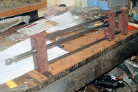 As
with most linear actuators there are two distinct functional
elements - one is the provision for guidance/constraint of
the moving rod and the other is the means of motion
generation or actuation. The guidance method I used is a standard
approach in linear motion systems design ie linear guide
rods with a ball bushing mounted moving block. The thrust
rod is fixed to the moving block and carried on a further
ball bushing where is passes through the fixed "neck" block.
The rods are all Ř16 steel which gives the guidance element
good rigidity. Ball bushings are preferred to plain sliding
bushes to minimise the friction levels and provide a
free-stroking slide system.
As
with most linear actuators there are two distinct functional
elements - one is the provision for guidance/constraint of
the moving rod and the other is the means of motion
generation or actuation. The guidance method I used is a standard
approach in linear motion systems design ie linear guide
rods with a ball bushing mounted moving block. The thrust
rod is fixed to the moving block and carried on a further
ball bushing where is passes through the fixed "neck" block.
The rods are all Ř16 steel which gives the guidance element
good rigidity. Ball bushings are preferred to plain sliding
bushes to minimise the friction levels and provide a
free-stroking slide system.
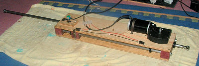
 The
motion generation is by closed-loop roller chain attached
to the moving block and driven by sprocket attached to the
drive motor output. The idler sprocket shaft also provides a
convenient position for mounting your position or speed
feedback device, I used a 5-turn potentiometer for position
feedback - approx 4.5 turns are used over the full stroke.
The
motion generation is by closed-loop roller chain attached
to the moving block and driven by sprocket attached to the
drive motor output. The idler sprocket shaft also provides a
convenient position for mounting your position or speed
feedback device, I used a 5-turn potentiometer for position
feedback - approx 4.5 turns are used over the full stroke.
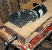 I
have used 3/8" pitch simplex roller chain which is widely
available and fairly inexpensive. Both the drive and idler
sprocket shafts are deep-groove ball bearing mounted. The
drive motor has a through-shaft worm gearhead and is mounted
on the drive sprocket shaft and secured to the actuator
wooden casing. It's current draw at its 9.35 Nm rated output
torque is about 12 Amps.
I
have used 3/8" pitch simplex roller chain which is widely
available and fairly inexpensive. Both the drive and idler
sprocket shafts are deep-groove ball bearing mounted. The
drive motor has a through-shaft worm gearhead and is mounted
on the drive sprocket shaft and secured to the actuator
wooden casing. It's current draw at its 9.35 Nm rated output
torque is about 12 Amps.
Actuator
mounting is by spherical bearing rod ends on the thrust and
tail rods. There is plenty of scope for fitting limit
switches on the casing which are triggered by the moving
block - important for implementing drive cut-off when the
actuator approaches its end-stops - see below! Driving onto
the end stops at full power is likely to damage the device -
it is a DIY design.
Performance
You can
get an idea of this from the two movie clips below. On the
prototype build the sliding guides work well and run freely.
The chain drive can also be set up so that there is very
little backlash and movement reversals are smooth. There may
be a small amount of backlash arising from the low-cost
drive motor's worm gearing but this doesn't appear to be a
problem. You can always amend the design to fit a higher
quality motor if you want - you get what you pay for with
these.
Clip 1 (unloaded),
Clip 2 (load "testing"
- don't do this at home!)
(Feb '08 - more movie clips of three actuators running
together can be seen on the
Platform 2 page here - this shows the actuators driven
by the single chip SPU with the PID servo controller in a
3-point platform setup.)
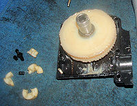 I
was slightly concerned about the possibility of vibration
coming through the drive rod from the chain transmission but
this doesn't appear to be very noticeable and would tend to
be present only at higher loads. The noise level is mainly
motor dependent - as is the norm with roller chain drives
the chain itself produces little noise. I made the mistake
of driving the actuator onto its end stops without
functional limit switches fitted and shattered the
motor/gearbox shaft coupling (see right). I had to replace
this with a home-made one and that's the main source of the
noise on the prototype. Moral of the story - don't power up
the actuator until your limit switches are fitted, wired and
functional!
I
was slightly concerned about the possibility of vibration
coming through the drive rod from the chain transmission but
this doesn't appear to be very noticeable and would tend to
be present only at higher loads. The noise level is mainly
motor dependent - as is the norm with roller chain drives
the chain itself produces little noise. I made the mistake
of driving the actuator onto its end stops without
functional limit switches fitted and shattered the
motor/gearbox shaft coupling (see right). I had to replace
this with a home-made one and that's the main source of the
noise on the prototype. Moral of the story - don't power up
the actuator until your limit switches are fitted, wired and
functional!
With the build of the second motion platform
I've been able to see the actuators run under load and the
performance is not bad. They are capable of driving the
balanced platform motion without significant motor heating
which suggests that the motors are not overloaded - this is
platform mass related off course. I've modified the design
(see V2 of the plans) to add a chain tensioning facility
which allows any chain slack to be adjusted out.
Backlash in the low-cost motor worm gearing is noticeable
during frequent heave reversals - higher quality gearing
would be better. However the effects could be reduced by
setting the platform up so that a net downward load on the
actuators is present - ie don't balance the weight
perfectly.
I've also made up a preliminary design
for a modification that would allow the Unite MY1018Z motor
to be used as an alternative. This is not worm geared but is
more readily available in the US than the MY7712NZ used in
the original design. I've not tested this modification - so
use with caution. The mod is shown in this .pdf sheet
-
ACT1-S004-1
- Preliminary MY1018Z Modification - Provided for
Information "AS-IS"
Plans
 I've
been able to make a detailed set of plans available for the
prototype design for information purposes. These are bundled
free with the motion drive software and are available to
customers who buy an unlock key for the BFF Motion Drive
software. AND they are included in the
Full Download Plans Set
available from the plans order page.
I've
been able to make a detailed set of plans available for the
prototype design for information purposes. These are bundled
free with the motion drive software and are available to
customers who buy an unlock key for the BFF Motion Drive
software. AND they are included in the
Full Download Plans Set
available from the plans order page.
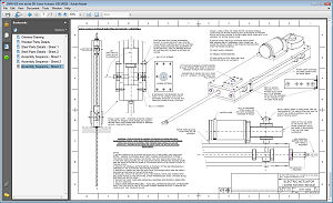
They are in the form of protected pdf engineering
drawing sheets and include a detailed materials and
components list. Note the plans are provided "AS-IS" and for
information only.
You can view the Overview drawing of the actuator
here
- the password is: actuator
© This site is
copyrighted, If you'd like more information or have any
comments please contact me at