 UPDATE
Jan '08, I've made available a series of high-resolution
CAD images of the main assemblies
of the motion cockpit for any other DIY'ers who are interested in
the construction principals - you can see them
here.
UPDATE
Jan '08, I've made available a series of high-resolution
CAD images of the main assemblies
of the motion cockpit for any other DIY'ers who are interested in
the construction principals - you can see them
here.
 For the FSX/FS2004 driven flight sim motion cockpit
I've gone for a three degree of freedom system – two rotational DOF's to simulate the forwards/reverse (fore/aft) forces and the
sideways (lateral) forces acting on the pilot, and a linear vertical
or heave DOF to try to deal with some of the vertical force effects. The fore/aft
forces arise mainly from changes to the aircraft's forward speed
(velocity) such as on take-off and landing, but also as a result of
the pitch attitude of the aircraft. Testing has suggested that lateral forces
during turns are generally light and mainly arise
from slippage effects but the roll motion is important in developing
a feeling of roll so there is a contribution
from the roll angle of the aircraft, and the vertical forces arise
from the heave movements of the aircraft in flight and also from
discrete events such as touch-down bumps on landing or running off
the end of runways (I know, I should practice more).
For the FSX/FS2004 driven flight sim motion cockpit
I've gone for a three degree of freedom system – two rotational DOF's to simulate the forwards/reverse (fore/aft) forces and the
sideways (lateral) forces acting on the pilot, and a linear vertical
or heave DOF to try to deal with some of the vertical force effects. The fore/aft
forces arise mainly from changes to the aircraft's forward speed
(velocity) such as on take-off and landing, but also as a result of
the pitch attitude of the aircraft. Testing has suggested that lateral forces
during turns are generally light and mainly arise
from slippage effects but the roll motion is important in developing
a feeling of roll so there is a contribution
from the roll angle of the aircraft, and the vertical forces arise
from the heave movements of the aircraft in flight and also from
discrete events such as touch-down bumps on landing or running off
the end of runways (I know, I should practice more).
Testing of the system has brought
up some surprises for me in which of these DOF's is the most active
under different flight conditions – mainly heave with not much in
the way of sideways accelerations.
|
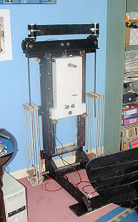
Support Frame
|
The working principal is to try to
simulate the force effects on the pilot - not to simulate the
apparent
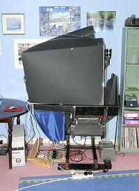
aircraft movements. Shown in a lower image the
flight sim motion cockpit is covered with a light-weight hood and when in
flight the pilot has no visual
signals of the external movements of the simulator – all he/she sees is the view of FS2004 on the computer screen and at the same time feel
forces that match what's happening in the virtual world
he's flying in. For a more lucid
explanation of this check out ForceDynamics' "how it works page"
here (and
while you're there watch their videos - that's performance that will
be hard to match).
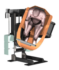
Looking at the CAD images you'll see
I've gone for a one-sided or cantilevered design for the flight sim motion
cockpit.
This is quite a bit different from most of the movement platforms
I've seen. It does introduce some
structural
challenges but it leaves one side completely open for pilot access and
reduces the overall footprint of the equipment. It is installed up against a solid wall which provides
much of the load support for the structure. The cantilevered
design also makes the heave DOF drive design relatively simple and
allows important counter balance weights to be incorporated into the
arrangement with out too much difficulty – all of which are
positioned away from the side where the users would congregate. The
arrangement also allows fairly generous movement ranges to be
designed-in which directly affect the range of flight conditions
that can be simulated – these are detailed below. Testing has shown
that I don't need all of the pitch and roll movement available,
although it does look like the more heave stroke there is the better.
The question of weight balance in the
system is important because it directly affects the power required
to drive the cockpit movements, and for a
given
set of drive motors it affects the response times they are able to
induce in the simulator. The lower the drive power required the
smaller the motors need to be and the cheaper the cockpit build will be -
power capacity affects most of the elements in the mechanical and
electrical power transmissions.
The rotational DOFs are brought into
balance by trying to ensure as much as possible that the axes of
rotation of the pitch and roll movements pass through the centers of
mass of the moving cockpit and pilot. This geometry is built
into the design and some minor adjustment should be possible by
slightly altering the seating position of the pilot. However the
heave DOF can only really be brought properly into balance by adding
counter weights, my provisional plan here was to use a number of
15kgf batteries for this because they are heavy, compact and I've
got several old ones sitting about. In the end I used a combination
of batteries and bungee or shock cord springs which reduces the
added mass in the system.
I have used four inexpensive
24V 200W DC PM motors to drive the movements. Two motors drive
the heave DOF which requires the most power, and one each
for the rotational DOF's.
Each motor is fitted with a worm gearhead which limits
to an extent the ability of the simulator to back drive through the motor and
helps the simulator hold position better without drawing much
power. It's important to say that the 200W rating of the motors is
their continuous use rating. Like most DC PM motors they are capable
of short term outputs much higher than this. It's modest commercial
aircraft levels of performance that the design is aimed at and it
looks as if it will be the heave DOF that will be most affected by
any power limitations there are.
I did the inertia and
acceleration sums and was interested to see what
the performance actually turned out to be. Generally the
power consumption is less than I anticipated. Only the heave
movement motors and controllers show any signs of warming
(indication of current draw) and the 20Amp speed controller driving
both heave motors stays well within its normal temperature range. I
suspect that less than 200W is needed for the two rotational DOF's.
Mechanical power
transmission is by roller chain drives which are quiet,
stiff, non-slip and relatively tolerant of misalignments
between the moving parts, they are also relatively
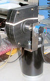
inexpensive to build. One unanticipated effect of the chain
drive on the heave movement was the transmission of chain on
sprocket vibration through to the cockpit at the higher
heave speeds. In the end I made
up and added a mechanical vibration isolation unit which
removed this vibration transmission - I have found that anything you can do to
smooth the movement improves the simulation effect.
Some technical details -
Heave displacement - +/- 200mm
(more if the structure height is increased, an advantage of using
counterbalance weights is that the heave DOF remains in balance over
the full stroke length). If I was to build it again I would add more
heave stroke length to give more scope for acceleration development.
|
|
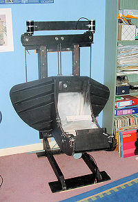
Support Frame
with Heave Cradle assembled
|
|
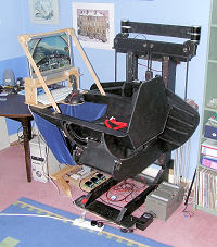
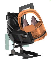
With Cockpit and
Screen Added - scope is there for a more realistic cockpit
fit-out.
|
|
Motionulated Forward Acceleration
- it became clear during testing that the full angle wasn't
needed to deliver strong force cues and the rig is now
limited to about +/- 30 Deg Pitch.
|
|
|
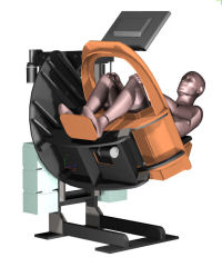
 Pitch - +/- 60 Degrees – the
pilot needs to be strapped in! Theoretically a 60 Deg pitch
backwards of the simulator simulates a forward acceleration of
nearly 0.9g . On testing it became apparent that to deliver
impressive force cues as much as +/- 60 Deg isn't needed. The normal
working range of the rig is now
limited to +/- 30 Deg, which also reduces the operating stresses on
the kit.
Pitch - +/- 60 Degrees – the
pilot needs to be strapped in! Theoretically a 60 Deg pitch
backwards of the simulator simulates a forward acceleration of
nearly 0.9g . On testing it became apparent that to deliver
impressive force cues as much as +/- 60 Deg isn't needed. The normal
working range of the rig is now
limited to +/- 30 Deg, which also reduces the operating stresses on
the kit.
Roll - +/- 40 Deg – enough to
simulate lateral accelerations of about 0.6g, again a fairly
respectable level. Again on testing it was clear that this capacity
was likely to be unused. In reality there is little lateral forcing
felt in a banked aircraft - especially if the turns are coordinated.
What does seem to matter in the simulator is cueing roll rate - ie
delivering a sensation of rolling that matches the on-screen
visuals. This can be done by rolling in the right direction but at a
lower rate and then slowly washing-out back to zero at a rate unnoticed by
the pilot. If large roll angles are maintained in the cockpit the
sustained sideways forcing felt by the pilot is not realistic. Where
this might be different is during ground manoeuvres - turns on the
ground do produce sustained lateral forcing.
However, it turned out that the
un-needed angle capability was in fact needed - but to provide a
runoff movement following triggering of the cockpit's limit
switches. It takes a moment for the movement to slow to a stop even
when the power is cut to the drive and the extra rotation allows
this deceleration to happen before the actual physical end stops are
hit. It was wise to design the capacity in - I just didn't use it
the way I'd intended.
(For interested readers the human model
shown in the CAD design is derived from body shells made
available by
M P Reed at the University
of Michigan. They are based on anthropometric data for crash
test dummies, data which also contains very useful mass and
inertia data - see his downloads page.)
The CAD images on the page show the
flight simulator motion cockpit in a range of operating positions –
the light-weight cockpit hood fitted on the built design but not
shown in the CAD images is very important for developing the
full effect of the simulation.
© This site is
copyrighted, If you'd like more information or have any
comments please contact me at