|

3-DOF
Platform 2 - Cockpit fittings and hood to be added |
MOVIE CLIPS
of Platform 2 in motion are on
Page 2 along with some photos.
Page 3 has dimensioned drawings.
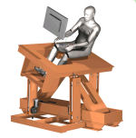
 JAN '08 After the experience of building the 1st
motion cockpit I thought it would be interesting to see
whether a more conventional 3-point support type platform
might be designed which would be a bit less complex
mechanically and so a bit easier to build. Keeping the cost
down was still an objective off course as was maintaining a
reasonable range of motion, including some decent heave
capability - many lower-cost 3-DOF platforms I've seen seem
to have very limited vertical stroke.
JAN '08 After the experience of building the 1st
motion cockpit I thought it would be interesting to see
whether a more conventional 3-point support type platform
might be designed which would be a bit less complex
mechanically and so a bit easier to build. Keeping the cost
down was still an objective off course as was maintaining a
reasonable range of motion, including some decent heave
capability - many lower-cost 3-DOF platforms I've seen seem
to have very limited vertical stroke.
My intention was to use
the DIY linear actuators I had worked on already to drive
the movements (more detail about these
here). Given their thrust
capacity (about 50 kgf ea. maximum) this would require that
the bulk of the weight of the platform and payload be
carried by a separate load support mechanism. The role of
the linear actuators is then primarily to accelerate
and decelerate the moving mass.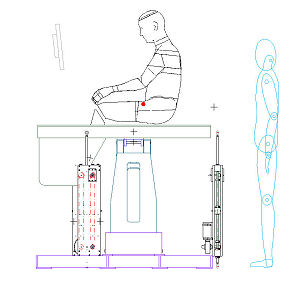 The load support mechanism
is also used to constrain unwanted horizontal linear
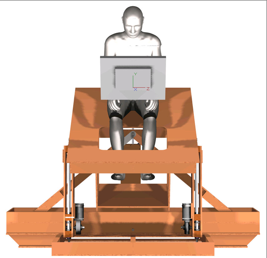
movements and yaw rotations. After
considering the options I went for two actuators at the front
and one at the rear - the center of mass of the payload is
likely to be closer to the front given the likely weight of
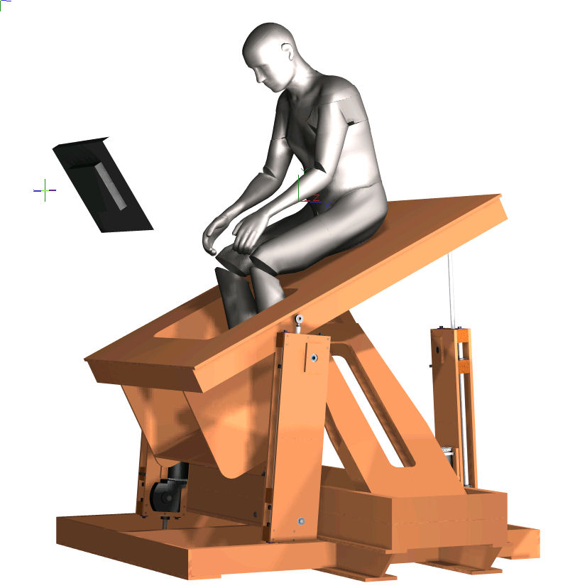
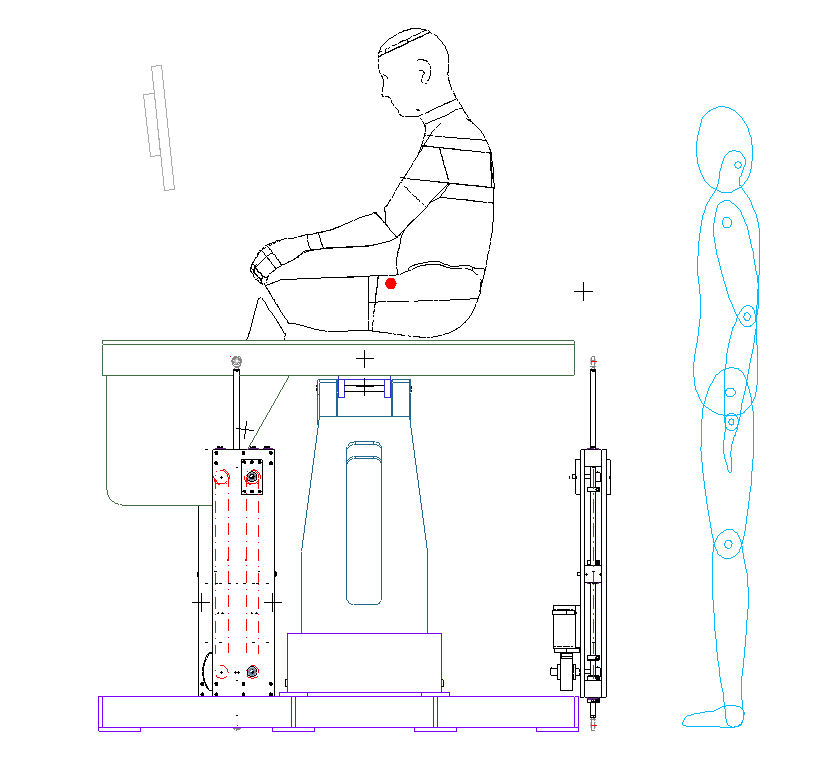
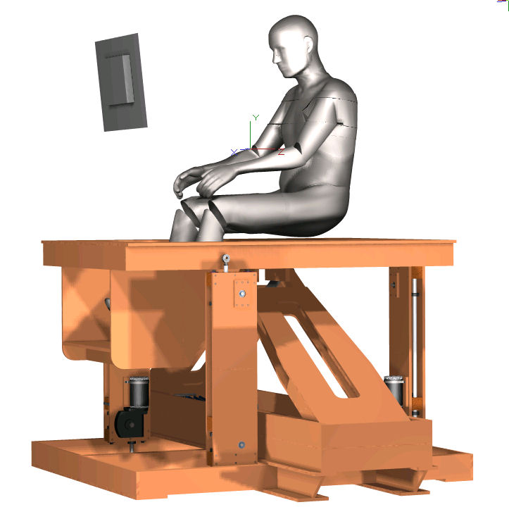
screens, instruments, controls etc. I've recessed the pilot's
legs into the platform in order to reduce the overall height, to
reduce the extent (and weight) of any superstructure required
and to move the payload center of mass down closer to the
physical roll and pitch pivot points.
The load support mechanism
is also used to constrain unwanted horizontal linear
movements and yaw rotations. After
considering the options I went for two actuators at the front
and one at the rear - the center of mass of the payload is
likely to be closer to the front given the likely weight of
screens, instruments, controls etc. I've recessed the pilot's
legs into the platform in order to reduce the overall height, to
reduce the extent (and weight) of any superstructure required
and to move the payload center of mass down closer to the
physical roll and pitch pivot points.
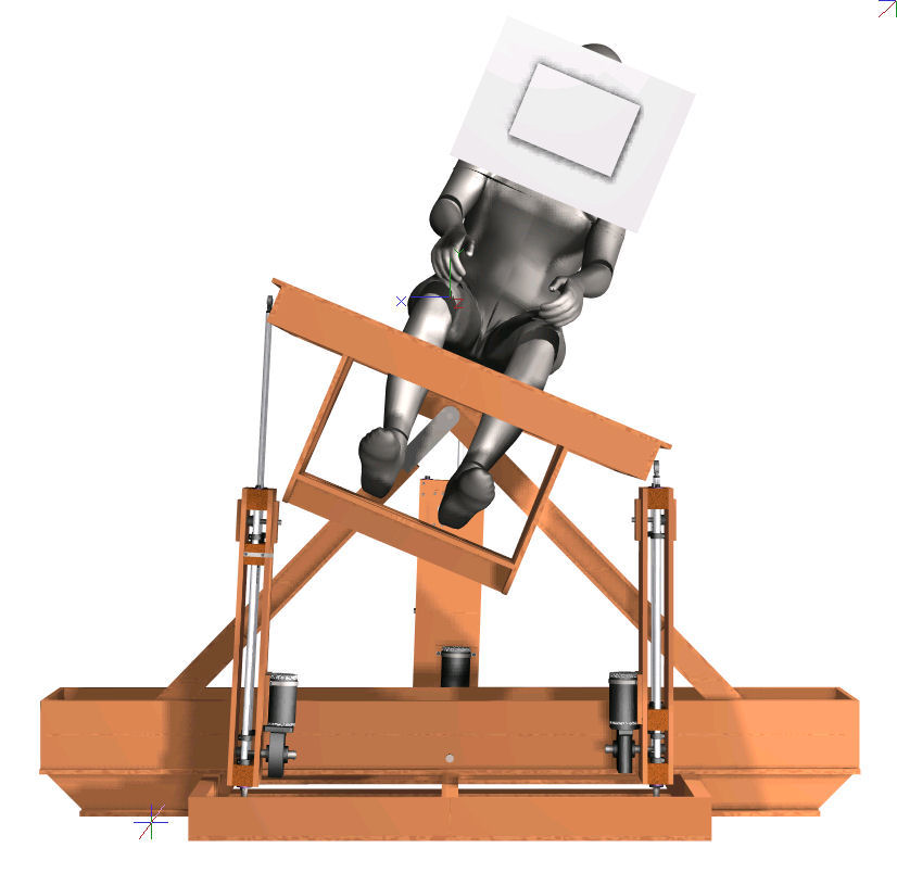
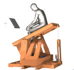
These pivot points, with the load support mechanism, are
positioned directly below the pilot and are probably a touch
further to the rear than I would like - however the pilot's legs
are where they are and clearance needs to be left for the pitch
movement. All designs require some compromises. Any resulting
pitch moment should not unduly challenge the actuator capacities
however - the main thing is to balance the vertical force.
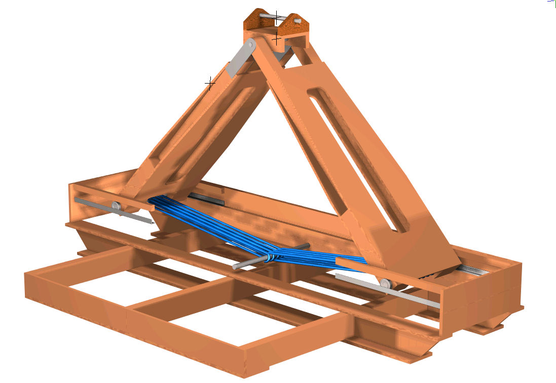
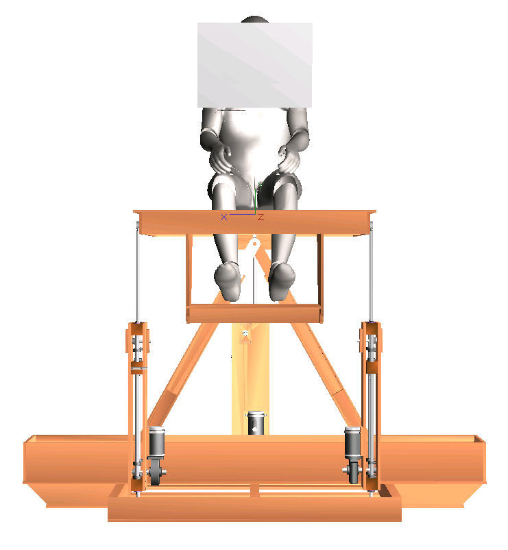
The
load support mechanism is a spring loaded half-scissors
mechanism. It has two legs in an inverted "V" arrangement pinned
at the top and running in horizontal linear guides at their
base.
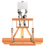
 The base of each leg is drawn into the mid-line of the
platform by bungee or shock cords which provide the spring
effect. Downward load on the legs from the platform through the gimbal forces the base of the legs to separate and stretch the
bungee cord which resists the force.
The base of each leg is drawn into the mid-line of the
platform by bungee or shock cords which provide the spring
effect. Downward load on the legs from the platform through the gimbal forces the base of the legs to separate and stretch the
bungee cord which resists the force.
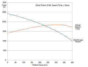
The trigonometry of the mechanism is interesting in that it
inverts the normal load/extension characteristics of a spring,
and with certain choices of spring stiffness produces a
sufficiently flat load/displacement response to be of use in
this application. The graph below shows the calculated spring
load and support load variations over the 30°
range of movement of the legs that match the 400 mm heave stroke
length of the platform. These profiles are based on Ř10mm bungee
- the total number of wraps determines the mean load carried by
the mechanism.
 The
arrangement would appear to avoid the need for added counter
balancing weights in the platform which should help to maximise
the motion performance with the DIY actuators. And bungee cord
is not expensive - so the problem of sourcing properly specified
springs is eased for the DIY'er.
The
arrangement would appear to avoid the need for added counter
balancing weights in the platform which should help to maximise
the motion performance with the DIY actuators. And bungee cord
is not expensive - so the problem of sourcing properly specified
springs is eased for the DIY'er.
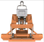
One of the main things that
becomes apparent when studying the overall design is the more
limited range of motion compared to the
1st motion cockpit with its
independent DOF's. Platform 2 will do about +/- 26° pitch, +/-
23° roll and +/- 200 mm heave - but not simultaneously. The
combined movement ranges are primarily limited by the actuator
stroke length of about 400mm. The 1st motion
cockpit does much better on the
pitch and roll angles and all DOF's can move to their full
limits simultaneously. So you pay your money and make your
choice with these designs - more performance requires more
complexity.
Most of the mechanical complexity on this design is contained
within the DIY actuators - the mechanism on the platform
contains mainly simple pivots and fairly straight forward linear
guides in the load support mechanism. The legs of the support
mechanism are pinned at both ends and consequently are in
compression. The gimbal is a simple cross pinned setup and the
remaining structures should be fairly straightforward to
construct.
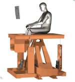
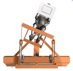
Click on the thumbnails below for some higher resolution images of
the CAD model renderings.

Have a look at the movie clips on
Platform 2 - Page 2 to see the
platform running shortly after its first assembly - still work
to do.
FEB '08 Update - build is in progress - 3 actuators
now running - see movie clips -
clip 1
clip 2
clip 3.
LATE FEB '08 Update - I've now managed to get the
new platform running and am getting a feel for how it
operates. So far so good and it generally seems to do what
was expected. Pitch, Roll and Heave movement are all there.
Platform 2 - page 2 shows some pictures and a few short
movie clips.
April '08 Update - Basic dimensioned
drawings of the parts are on Page
3. Provided free of charge for information purposes.
© This site is
copyrighted, If you'd like more information or have any
comments please contact me at