Motorised Trim Wheel for Flight Simulators
NOW AVAILABLE!
STL files for the 3D
Printed parts are
available here (updated Sept 17)
(Feb 21 - Customer contributed
Cessna style wheel .stl file as option)
This GA aircraft style trim wheel is manually
operated to set trim in normal flight, then when auto-pilot is
active it automatically rotates to follow the A/P pitch
control actions (stepper motor driven).
IMPORTANT: As with most projects on the site
this is a DIY build project. The driver card and 3D printed
parts are available to buy, but to complete the project you
will need to source yourself the other parts such as stepper
motor, feedback pot, indicator servo etc. See the
purchase
information page for more details.
TRIM WHEEL FEATURES
-
Integrates directly with FSX/P3D/X-Plane as
standalone unit, or can be used with the BFF Control Loader system
-
Turn by hand to set trim manually
-
Automatically follows FS trim movements when A/P is
active or when electrical trim buttons operated
-
180mm trim wheel dia, 4.5 Revs working
range (5 revs hard stop to hard stop - set by
potentiometer rotational range)
-
Working range adjustable in settings
(soft stops)
-
Built in RC Servo driven trim position
indicator
-
Built-in potentiometer provides trim
position feed to FS via FSUIPC or XPUIPC.
-
Base or side mounted
-
Left or right hand mounting (trim wheel
and indicator direction reversible)
-
Full supporting BFF Trim Wheel software
-
3D Printed parts throughout (.STL files
are available if you want to try your own)
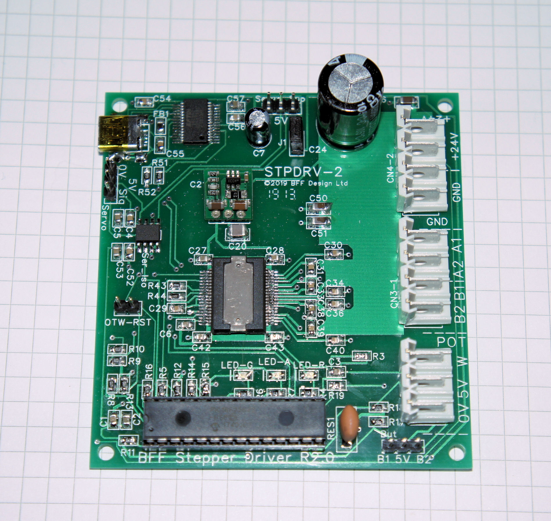
STPDRV-2 card TECHNICAL DETAILS
-
Drives bi-polar steppers with 2 phase
sinusoidal voltage drive for smooth operation
-
Input voltage: 24V
-
Stepper output voltage adjustable from
2.4V to 24V to suit motor. Default is 12V for specified
trim wheel motor
-
TI DRV8432 drive chip will drive most
small steppers without heat sinking, output currents can
be increased with additional heat sinking to drive
larger motors
-
Includes over-temperature and other chip
fault protection
-
Potentiometer input, electric trim
buttons, servo power in and servo out connections
-
Indicator servo output electrically
isolated from USB and stepper drive circuits
-
Separate 5V servo power required (approx
500mA)
-
USB Mini-B Connection - no virtual COM
port required
-
Status LED's and full card status reporting to
software
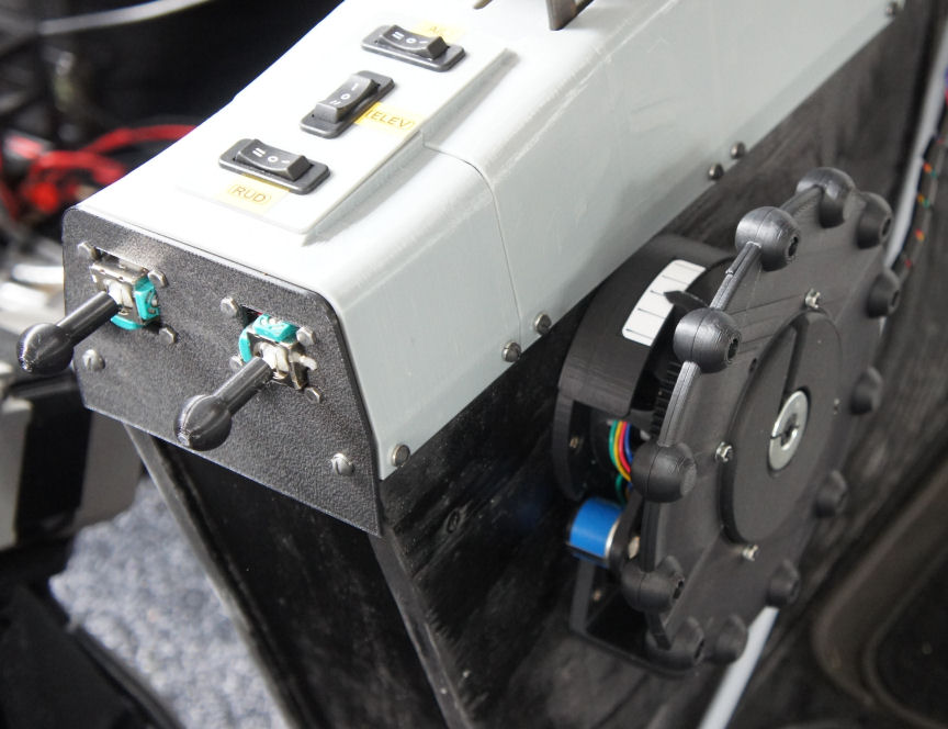
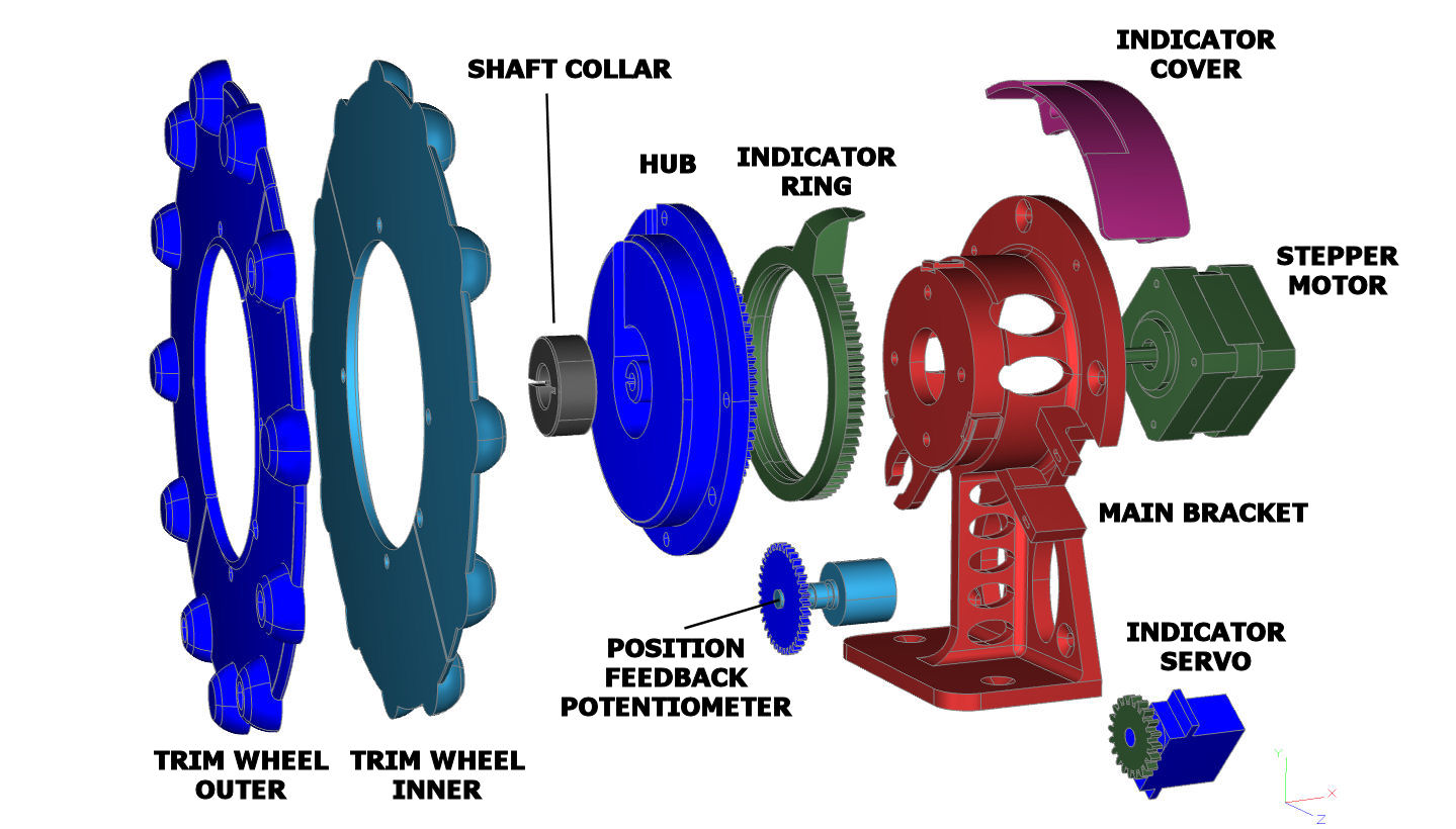
MECHANICAL ARRANGEMENT
|
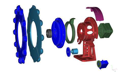
BFF
Motorised Trim
Wheel Assy - exploded view |
The trim wheel assembly can be base or side
mounted in your cockpit. It can also be mounted in a right
or left hand orientation to allow location on the left or
right side of a centre pedestal (the nose-up/down direction of travel of the
trim wheel and of the position indicator can be reversed to
suit). The unit can also be rotated for attachment to hide
the body of the stand behind the wheel.
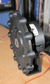 The trim position indicator and cover can be
rotated about the wheel axis to customise the indicator location.
The trim position indicator and cover can be
rotated about the wheel axis to customise the indicator location.
The mechanical components of the trim wheel
are 3D printed. I use a Zortrax M200 printer with Z-HIPS
material which gives good dimensional accuracy and a good
surface finish to the parts.
A full set of printed
components available to buy.
I have also made the STL files available if you
wish to try printing the parts yourself.
The
STL files for the 3D printed components are here.
Good dimensional
reproduction is needed on the geared parts (the trim wheel
hub, and the pot and servo gears) to ensure smooth meshing.
In addition the centre holes on the hub and pot gears will
need to be drilled through accurately to give good press fit
location on the motor and pot shafts (5 mm on motor, 6.35 mm
(1/4")
on pot). This is a better way to produce the required
accuracy of fit as opposed to trying to print to the
required shaft hole diameters. Please check the readme
documents in the zip for more information.
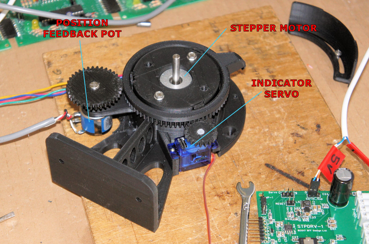
|
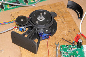
BFF
Motorised Trim
Wheel Assy
with wheel removed |
The bought components used in the trim wheel
assembly are:
-
Stepper Motor:
Mercury Motor
SM-42BYG011-25, see
https://www.sparkfun.com/products/9238
-
Position
feedback potentiometer: Vishay Spectrol Model 534 (10
turn, 10KOhm, Linear)
http://www.vishay.com/ppg?57065
-
Indicator Servo:
Any good quality 9g micro-servo, for example:
https://www.servoshop.co.uk/index.php?srch=SG92R
Check it can handle the 0.8ms to 2.2ms pulse length
range output by the STPDRV-1 card. You may also want to
buy an extension cable for the servo if you wish to
mount the STPDRV-1 card a bit further away from the trim
wheel - the lead length on the 9g servo will not be
much.
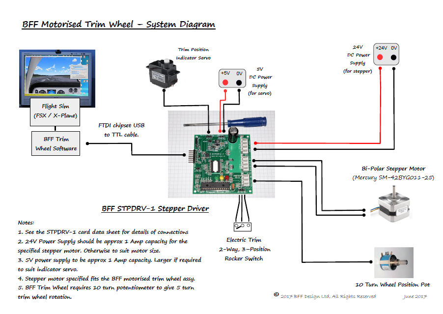
SYSTEM CONFIGURATION (Shows older
STPDRV-1 card)
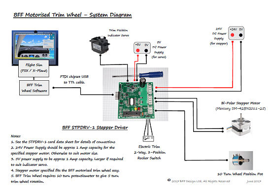
Please see the
STPDRV-2 card datasheet for
details of the connections.
The card provides connections for the stepper
motor, position reporting pot, indicator servo, USB/TTL
cable, electric trim buttons and 24V and 5V (servo) power
inputs. The logic side of the card is powered directly from
USB, and the 24V power input supplies the main drive chip
and stepper motor. The indicator servo drive is electrically
isolated from the rest of the card and requires a separate
5V supply. For full isolation the 5V supply should not share
the same ground as the main 24V supply. If your servo is
electrically quiet the card may still operate properly with
shared grounds.
The current draw by the stepper motor and
servo are low - so power supplies with approx 1 amp
capacity should be sufficient. If the card is used to drive
larger steppers or servos then the power supplies should be
sized to suit and additional heat sinking should be added to
the drive chip..
SOFTWARE
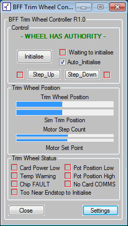 The
trim wheel is operated and controlled using the BFF Trim
Wheel software. This provides control and monitoring
facilities for the wheel and card.
The
trim wheel is operated and controlled using the BFF Trim
Wheel software. This provides control and monitoring
facilities for the wheel and card.
The software controls the power-up initialisation of
the wheel, provides manual control of the stepper and servo
drives, provides settings and wheel and card status
monitoring.
On power-up initialisation the wheel will
rotate automatically to determine drive sense and working range. When this is completed the operation is largely
automatic - the wheel can be turned manually to adjust trim
position in normal flight. When A/P becomes active the wheel
will automatically follow the trim position.
The software will display wheel positions and
card status to allow operation to be monitored, otherwise it
can be left to its own devices.....
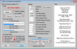
The window expands to display the
settings area. User settings include stepper output voltage,
wheel working range, position following response
sensitivity, manual stepping speed, direction inversion etc.
The app can also be run when FS/X-Plane
is not available. In this mode the manual motor and servo
control is active. This is particularly useful during the
wheel build and set up stages.
The software also supports operation of the
trim wheel with the BFF Control Loader system. In this mode
the wheel operation is fully integrated with the CL system.
Manual adjustment of trim wheel position adjusts trim tab
position and hence trim force level. And when A/P is active
the trim wheel will move automatically to simulate minimising the stick
force when the main elevator axis is following the A/P pitch
control actions.
To enable trim wheel integration the CL system must be
configured accordingly. See the CL system Configuration
Manager (V1.16+) Tab 7 Item 25.
For use with X-Plane XPUIPC is required.
If you can't
get to the XPUIPC website here's DropBox links for XPUIPC -
V1.9 and
V2.0
© This site is
copyrighted, If you'd like more information or have any
comments please contact me at