For some other CL
system related images see the
Gallery
Some Customer Installations
Air Tractor Training Simulator (Alberta, Canada)
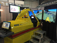 At the back end of 2014 I
supplied a 3-axis pre-assembled control loader drive
to
Western Air Spray in Canada.
It was installed in their new Air Tractor simulator
this year and saw initial service at a trade show
this spring (2015).
At the back end of 2014 I
supplied a 3-axis pre-assembled control loader drive
to
Western Air Spray in Canada.
It was installed in their new Air Tractor simulator
this year and saw initial service at a trade show
this spring (2015).
The system uses double stage chain reductions for
its transmission which work well but are reported by
the builder to be fairly maintenance intensive.
More details of
the build are provided on a dedicated web page
here....
Cessna 182RG Project (France)
|

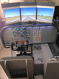
Yoke mechanism with card enclosure
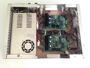
Motor driver cards and power supply in
enclosure... |
Here's a recent customer's implementation of
the DIY FFB Flight Yoke in a Cessna
182RG simulator in France. The yoke mechanism is located
behind the instrument panelling and the BLDRV-12/24 motor
driver cards are installed in the electrical enclosure next
to it.
Benjamin has done a great job on both the
mechanical and electrical build with a few subtle
modifications for belt tightening and structure stiffening.
He hopes soon to add an update on the system on his web site
here...
www.simu182rg.fr (site in French)
Heavy Jet Builds
The BFF control loader drive and
software isn't only suitable for use in the
DIY FFB Flight Yoke design
shown here. It can also be
built into other designs of flight controls. This includes
twin flight column setups typically seen in heavy jet
cockpits. Several customers have taken this approach and
implemented force feel in their heavy jet cockpits
(including in sims used for flight training).
The force output of the system is effectively
only limited by the design of the mechanical transmission
which connects the drive motors to the controls (although
good quality design and components are required so as not to
compromise the good force feel).
Below are a few examples....
Czech DC-9 Project
This
Douglas DC-9
cockpit restoration project is a work in progress in the
Czech Republic. The team intend eventually to add control
loading to all three control axes and at present the
elevator force feedback is up and running and integrated
with the original cockpit control mechanisms.
For more information see the Photos and
Videos sections of the
project's web
site.
The CL drive on the elevator uses a motor /
planetary gear head with crank arm to apply the force
feedback to the flight column. This is proving effective in
transmitting the loading without backlash into the control
mechanisms. The design target peak force in the elevator
axis is 20 kgf (44lbf) which is a fairly hefty load to
grapple with....
Here are a couple of videos from the team
showing first the elevator control loading in action, and
then some views of the under floor mechanisms.
The drive gear box aluminium crank arm can
just be seen at the back in this video....
Thanks to Pavel and Petr for allowing linking
to their movie clips...
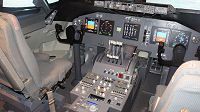
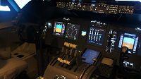
SWESIM 737 Simulator
SWESIM
now have a 2 axis BFF CL system fully operational on their
737-800 simulator in
Sweden (web site in Swedish).
Theirs is a very interesting build also. They
have taken a different route to that described below for the
AERSIM project to the design of the mechanical
transmissions which connect the CL system brushless drive
motors to the flight controls. They have used a drive motor
with directly fitted planetary gear head and crank arm for
the elevator drive, and an interesting cable wire and pulley
drive to their aileron axis.
The gear head option provides a mechanically
simpler method than the belt pulley reduction units used by
Romek (see below) and is an attractive solution to consider so long as a good
quality gear head is used.
Here are a couple of YouTube videos showing
their system during build and commissioning...
This first video shows the flight control
mechanical assembly before installation - you can clearly
view the motors and transmission mechanisms - an interesting
build!
This second clip shows the system installed
and during setup and commissioning.
SWESIM reports that the system is
now fully operational and getting "very positive" feedback from real B737 pilots who
have tested the sim.
Many thanks to Erik at SWESIM for allowing me to link
to their site and videos.
|
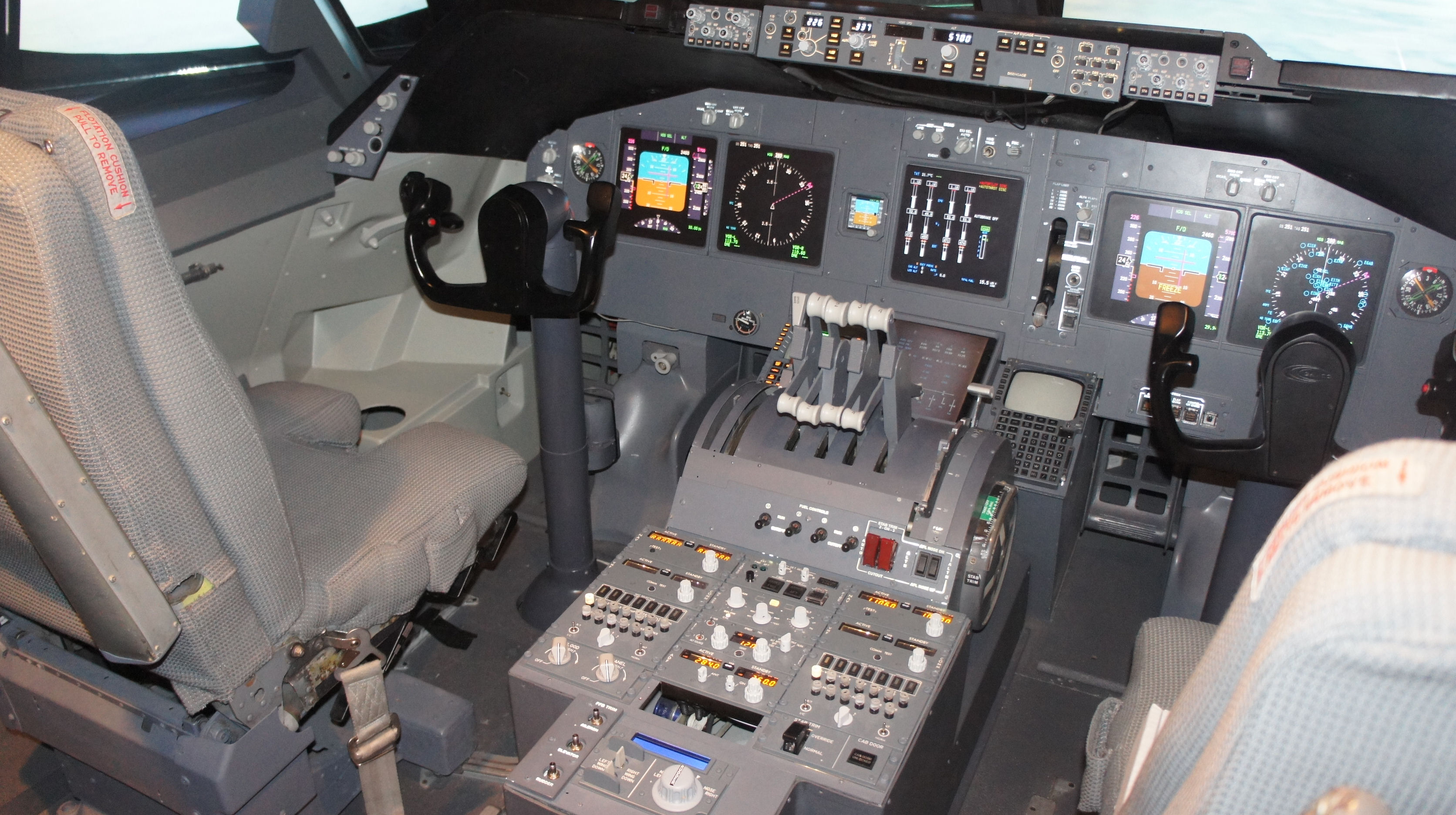
AERSIM 747 Simulator |
|
Romek Delimata's Aersim 747 Simulator - fitted with
the BFF Flight Control Loading system. |
AERSIM 747 Simulator
The BFF flight control loading system has
recently been installed by Romek Delimata on his Boeing 747
simulator near Dublin.
Romek has designed his own drive mechanisms
to interface the brushless drive motors to his existing
elevator, aileron and rudder controls. A single brushless
motor is used to drive each axis of the dual-control set up.
The CL system consists of 3 BLDRV-12/24 cards
driving 3 brushless motors all instructed by the BFF CL
Software. The 747 sim runs FSX.
In addition to the normal variable force feel
and force trim effects to the simulator the CL system also
introduces believable vibration effects into all the
controls. Some of this vibration also transmits into the
airframe. The effect is to bring the controls alive with
variable vibration levels which reflect the level of engine
thrust or runway speeds.
Romek has also suggested adding spoiler
buffeting, other vibration effects such as landing gear air
buffeting would be worth considering.
Customer Comment: "The BFF force feedback
system is the biggest single improvement I've added to the
simulator in the 12 years I've been working on it, having
proper FFB provides a quantum leap in realism and makes it
far easier and more intuitive for professional pilots to
fly, the FFB provides all sorts of subtle yet very powerful
cues that really connect you with the forces acting on the
aircraft, in my opinion it's better then a motion system - I
can't recommend the BFF FFB system highly enough - well done
Ian on a ground breaking product."
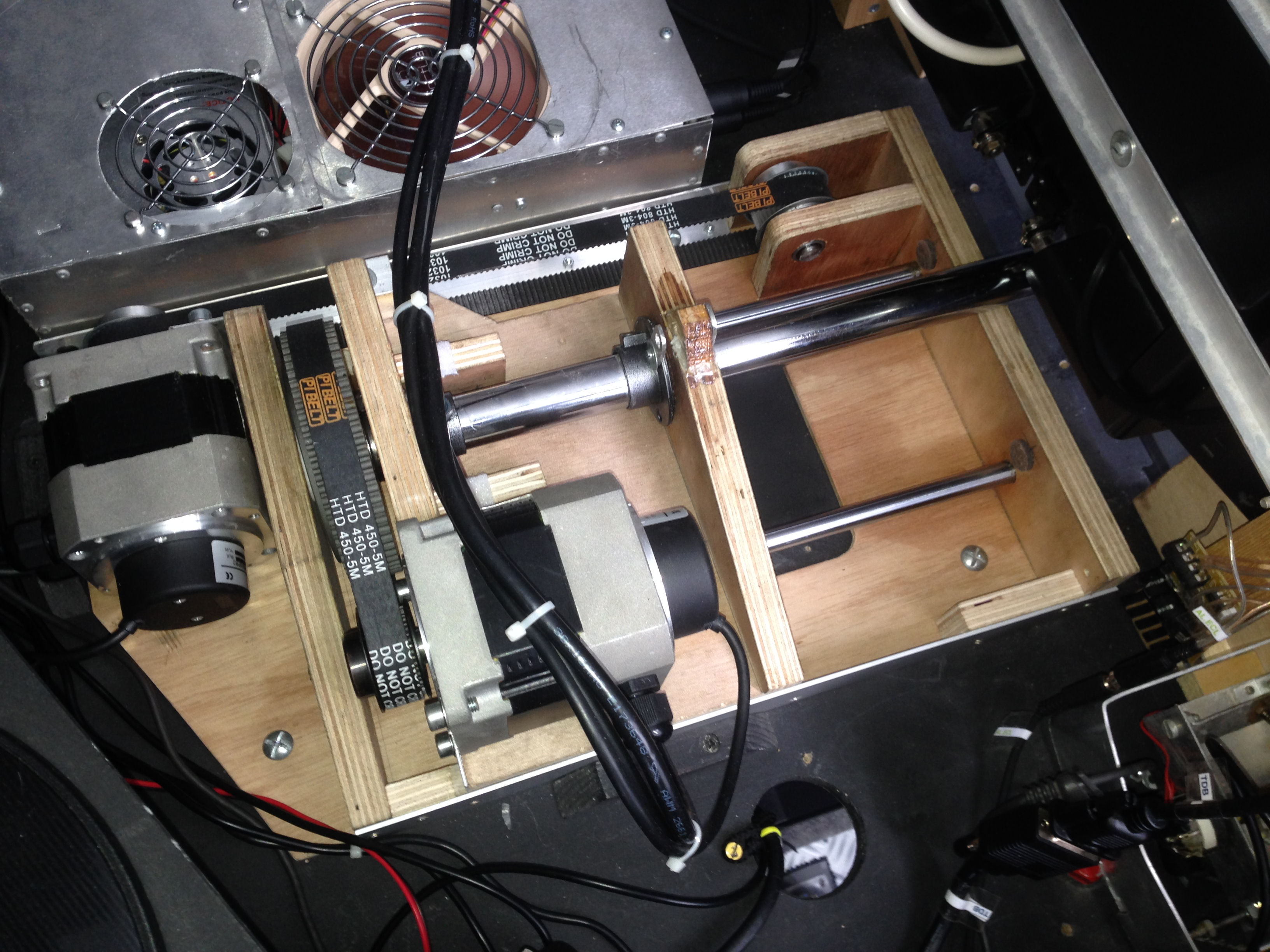
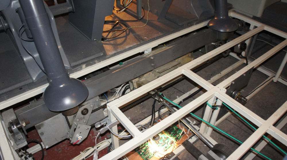
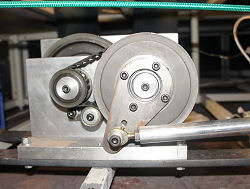
Here are a few photos showing some of the
drive setup - thanks to Romek for allowing me to
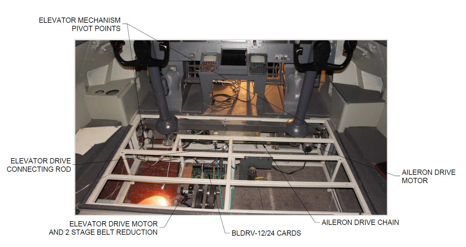
use these. The image below shows the elevator and aileron
mechanisms which are located under the floor of the sim.
Both the elevator and rudder controls are
driven by a crank arm / connecting rod arrangement. The
connecting rod connects a short crank arm on a 2 stage belt
reduction unit to a longer crank arm added to the existing
elevator pivot mechanism. A similar efficient back-driveable
reduction could be achieved using a planetary gearhead
mounted on the motor.
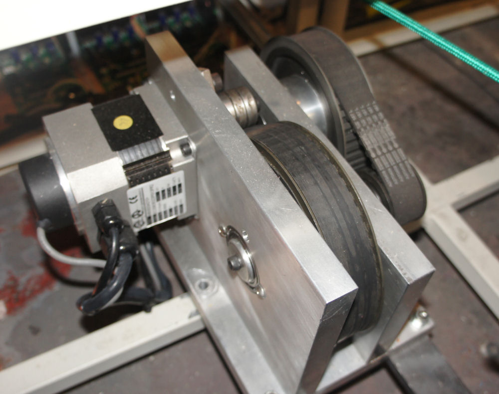
 |
 |
|
FFB Drive Crank Mechanism details |
The aileron control axis is driven by roller
chain to which the aileron axis brushless motor is
interfaced.
You can see some of the aileron roller chain
in the image left - the chain loops up each flight column to
the control wheels. The whole of the aileron drive mechanism
is mounted on the pivoted elevator assembly.
Unfortunately the rudder pedal drive
mechanism is snugly fitted under the panel area and can't be
seen all that clearly in photos. However it utilises an
identical 2 stage belt reduction unit and crank arm to drive
the existing dual pedal mechanism to produce the force
feedback.
© This site is
copyrighted, If you'd like more information or have any
comments please contact me at