Firmware Update
Procedure
Current Firmware:
Beta22 (1st Oct 2013)
Change Log:
B22 - Corrected intermittent spikes
appearing in PWM3 & 4 outputs.
Update Procedure:
1. Download the above
firmware and unzip the two .bas
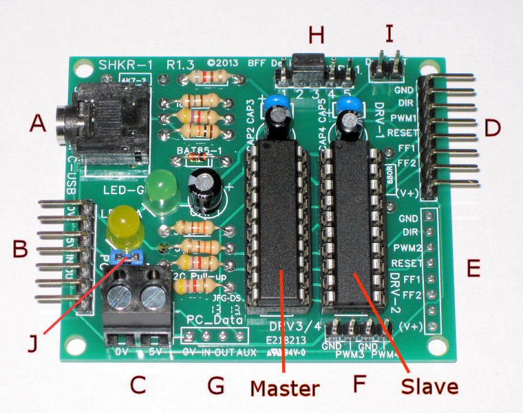
files to your PC. The files contain
the programs for the master
and slave chips - see image.
2. Download and
install the PICAXE Programming
Editor software from the PICAXE web
site here:
http://www.picaxe.com/Software/PICAXE/PICAXE-Programming-Editor/
3. Remove power from
the shaker card. Remove power from
your Pololu driver and disconnect
any other audio feeds.
4. Start the PICAXE
Programming Editor. Go
to Options-Serial
Port and set the COM port to the
port number for your cable to the
shaker card.
5. Put the SHKR-1
card into programming mode by
changing the jumper settings on 5
pin header JMP-1 (H in picture
above). In normal mode pins 2 & 3
are connected on this header. For
programming mode pins 1 & 2 are
connected, and pins 4 & 5 are
connected. You will need another
jumper link to do this.
6. Carefully remove
the "Slave" chip from its socket. In
programming mode only the "Master"
socket can be used to program the
chips. Leave the "Master" chip in
place. You will re-program the old
master chip as the new Slave.
7. In the Programming
Editor go to File-Open and select
and open the new Slave .bas
file. DO NOT CHANGE ANYTHING IN THE
FILE.
8. Apply power to the
card (logic end only - NOT Pololu
driver power).
9. Click Program
- a progress
bar should appear and show the
programming status, the editor will
indicate completion.
(If the editor can't
make contact with the chip you may
have to do a "hard reset" - to do
this remove power from the card,
click Program again - and then
immediately re-apply power to the
card. This should force the chip
into programming mode).
10. When complete
the newly programmed chip is now the
new Slave - remove it
from the socket and set it aside.
11. Now fit the
other chip to the master socket and
repeat the above programming steps -
but this time load the Master
.bas file into the programming
editor. (Note the correct
orientation of the chip - the
location dot on the chip surface
should be closest to the 5-pin
header (H) end of the socket.)
12. Once programming
is complete this chip is the new
Master chip and can be left
where it is - in the master socket.
Remove power from the card and fit
the new Slave chip to the
other socket - make sure of the
correct orientation of the chip.
13. Close the
Programming Editor.
14. Return the 5 pin
header JMP-1 (H) to normal operation
mode by fitting a single jumper to
pins 2 & 3.
You can now run the
SHKR-1 card with its new firmware.
© This site is
copyrighted, If you'd like more information or have any
comments please contact me at