DIY Motion Platform Servo Drive System -
64SPU-1 Card
|
NOTE An
un-programmed version of the 64SPU-1 is now
available for use in your own DIY electronics
projects.
More details here |
UPDATE March 2015, IMPORTANT - the
64SPU-1 has now been superseded with the NEW
64SPU-2 card - see here for more
details.
UPDATE March 2013, for an excellent
example of a drive system build using the 64SPU-1 and other
cards please see Roland van Roy's write-up here -
http://simprojects.nl/electrical_drive_iv.htm
Roland has helpfully provided advice and
his technical wiring diagrams for his system on the page.
The motion platform servo drive system
developed for the DIY platform projects described on the web
site has evolved through several versions to what is now a
compact and effective low-cost DIY motion platform servo drive. The
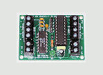
home-made
Signal Processor Units I previously built on a PICAXE
breadboard kit have now been replaced with a small standalone
PCB that incorporates all the previous features of the SPU's and adds
several important enhancements. The 64SPU-1 card is
available to buy now.
The 64SPU-1 card works with the
BFF PID Servo Controller software
to provide a functioning servo control system.
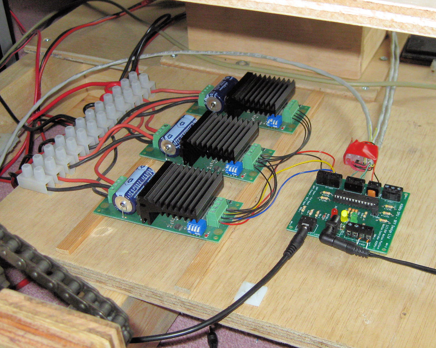
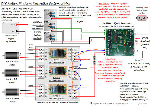
Illustrative system wiring below: (for
use with alternative Dimension Engineering Sabertooth /
SyRen controllers see here...)
|
|
Optional Cards
BFF I2C Isolator card
For noise protection of the
64SPU-1 on electrically noisy servo systems.
12ADC-1 12bit pot
feedback converter card - upgrade to 12bit
feedback resolution. |
The main components that make up the DIY motion
platform servo drive are
now:
-
The 64SPU-1 64MHz Signal Processor Unit
card - available to buy now - see the order pages
here.
-
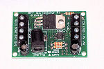
Devantech
MD03 Motor Speed Controllers - 24V 20 Amp DC
controllers delivering up to 480 Watts of electrical
power per controller.
-
24V DC PM Motors to suit the DIY
platform project. The MD03 controllers will support up
to a nominal 20 Amps rating, sustained currents above this
level will cause overheating and current limiting by the
MD03's.
-
Position feedback potentiometers (10
bit), or, recommended for smoother drives, the
12ADC-1 12bit ADC card or US Digital
MA3 position encoders (12bit PWM). (Pots/encoders fitted to the
drive actuators or elsewhere on the platform to report
actual platform position.)
-
DC power supplies for the drive motors
and electronics.
-
Actuator travel limit switches, fuses,
cables and wiring.
PLEASE NOTE - I am not able to supply all of
the above hardware, just the 64SPU-1 card, the
BFF I2C Isolator card ,
12ADC-1 12bit ADC card and motion
software. If you want to build the servo drive for your own
project then you will need to source the motors,
controllers, encoders, switches etc etc yourself.
IMPORTANT - The 64SPU-1 card is part of a
closed loop position feedback servo drive. The position
feedback potentiometers/encoders shown on the wiring
diagrams MUST be fitted to the drive motors/actuators to
report platform position to the 64SPU-1 card. Without this
the closed loop position control can NOT operate. If you are
not sure what a closed loop position control servo drive is
then I recommend you try and read-up a bit before attempting
to use this hardware. It is very important to understand
that this is not a "plug and play" system intended for
consumer use - it is intended for use by informed DIY system
builders. Read both the motion software user manual and the
64SPU-1 data sheet before using the hardware.
|
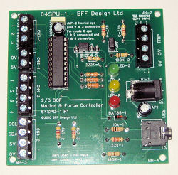
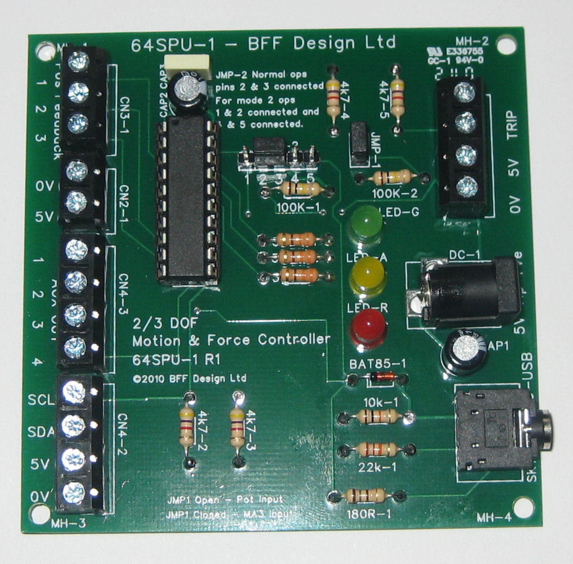
64SPU-1 Signal Processor Unit
For DIY Motion
Platform DC Servo Drives |
64SPU-1 Card - The new
64SPU-1 signal processor card is at
the heart of the servo drive and acts as the
communications bridge between the MD03 motor controllers, feedback pots/encoders and the BFF PID Servo Controller
software running on the PC. It also acts as a system
monitoring and information feedback unit - it monitors for
communications interruptions and stops the motor drives when
required and also
feeds back MD03 current and temperature information to the
Servo Controller software.
The 64SPU-1 is available to buy as a
ready-to-connect card (80 mm x 80 mm) which removes the need for all the
delicate breadboard wiring of the
previous DIY versions.
For full details read the 64SPU-1 data sheet
-
64SPU-1 Data Sheet
The main features of the 64SPU-1 are:
-
I2C data output for use with Devantech MD03 motor speed
controllers.
-
2 or 3 channel output for 2 or 3 DOF motion systems.
-
Selectable Potentiometer (10 bit) or MA3 Digital Encoder
(12 bit) actuator position feedback. Potentiometer
feedback can be upgraded to 12bit resolution using the
12ADC-1 card.
-
Built-in fast smoothing on the potentiometer feedback to
reduce signal noise. Use with the
12bit 12ADC-1 card for best potentiometer feedback
smoothness.
-
Built-in “Pause Output” or "Drive Enable" trip loop.
-
64MHz operation giving up to 50Hz control loop refresh
speeds (up to 70Hz when used with the
12ADC-1 pot feedback card).
-
Direct connection to PC USB or Serial port (physical
serial port recommended for fastest speeds). 115200 baud
serial comms.
-
LED status indicators, screw connectors.
-
On-board 20X2 microcontroller re-programmable in-situ
for firmware upgrade or customised output programming.
The card is available to buy on its own or bundled
with the V2 Motion Driver software -
see the order page here.
(NOTE - Data Sheet for superceded 40SPU-1
card can be found
here...)
SERVO SYSTEM OPERATION
|

40SPU-1 and
MD03 motor
controllers on
test |
The servo system hardware works in
conjunction with the BFF PID Servo Control software running on
the PC.
The servo software receives platform position demand
information from the BFF Motion Driver and
also receives actual platform
position feedback data from the position feedback
pots/encoders connected to the 64SPU-1 card. Using this data it calculates
motor speed demand outputs which control the direction and
speed of the actuator drive motors to drive the
platform to the demanded positions. The motor control
commands are sent to the MD03 motor controllers via the
64SPU-1 signal processor card.
The servo control loop can run at up to 50Hz
(PC and connection dependent) - ie the speed and direction of each motor is
adjusted by the system up to 50 times each second and this
makes for an effective system response under most platform
motions. For the best performance it is better to run the
motion software on a LAN PC separate from the flight sim PC.
If the 12ADC-1 12bit potentiometer
feedback converter card is used the servo loop can run at up
to 70Hz.
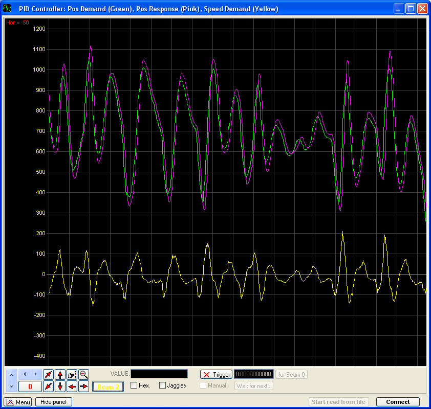
|
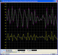
An example
actuator trace
(using the PID
Controller's built-in
virtual
oscilloscope). |
The servo software uses a PID (proportional -
integral - derivative) control algorithm and the PID
parameters that define the control response can be set through the BFF Servo Controller GUI.
This makes tuning the servo system easier as small changes
can be made to the control algorithm and the resulting
effects on the motion assessed immediately.
Actuator limit switches and an Emergency Stop
switch should be wired in series in the 5V supply line from
the 64SPU-1 to the MD03 motor controllers to cut the drive
to the motors to prevent damage if the actuators over-stroke.
The 64SPU-1 also includes a simple trip loop into which a
"Pause Output" or "Drive Enable" switch can be wired.
Motor controller "live" current and
temperature data is continuously fed back by the 64SPU-1 to
be displayed on the PC by the BFF Servo Controller software.
This makes for interesting viewing, however it can also be
of significant assistance during platform set-up work as it
provides a
direct indication of the system electrical loading. The servo software also
includes a virtual
oscilloscope to view demanded and actual actuator positions
and motor speed demand.
|
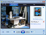
Video clip of
the older 40SPU-1
driving the
Mini Motion
Platform. NB
The platform is being driven with no pilot load
so against the unbalanced force of the support
column spring. |
For the best performance of the servo drive I
find that 12bit position feedback (using either
MA3 absolute position encoders
or pot feedback via the 12bit 12ADC-1
card) should be used for the
position feedback, and the 64SPU-1 should be connected to the
driving PC through a physical Serial (COM) port. If you are
using the PICAXE USB Serial cable then it also can give good
results by reducing the "Latency Timer" setting to 1 ms in
the relevant COM port's advanced settings.
Overall the 64SPU-1 and associated servo
software can provide an effective servo drive for DIY motion
platforms at a seriously low price. The 64SPU-1 is however a
relatively simple card and although it contains a number of
safety features such as comms time-out monitoring, some
feedback error detection and feedback limit detection the
price does not allow the types of system monitoring
capabilities that can be found on much more expensive commercial motion
controllers. You must take care to ensure the platform
drive is properly protected by over-travel limit switches
and an accessible Emergency Stop button.
Although there are some electrical noise
isolation features on the card in particularly electrically
noisy systems the on-board 20X2 microcontroller can be
affected by voltage spikes coming through on the 5V and
ground lines. The source of such electrical noise is usually the
drive motors. For added reliability the
BFF I2C Isolator card can be
used with the 64SPU-1 to fully isolate it from wiring bourn
noise propagating from the electric drive motors through the
MD03 logic ground connections. The
isolator card allows the
64SPU-1 to be powered from its own independent clean 5V
power supply.
If you wish to buy the 64SPU-1 please read
the data sheet
carefully and follow the installation and use
recommendations.
© This site is
copyrighted, If you'd like more information or have any
comments please contact me at