UPDATE - This
page describes an early development of the servo control
system for the DIY motion platform. As of Summer 2009 a new
ready-built control card - the
40SPU-1, is available to buy which replaces all the
breadboard electronics. See the
40SPU-1 page for more up-to-date details.
The Signal
Processor and its
PICAXE chips work with low currents – nowhere near enough to
directly drive
the 200W DC motors used in the cockpit. This task is carried out in the system using bought speed
controllers. I've used several of these on the various
electric vehicle projects you can see on the rest of the
site and I thought initially I'd go with controllers I was
already familiar with for the movement cockpit prototype.
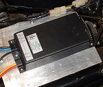
Specifically I looked at three of 4QD's 24V Vortex
controllers - a 35Amp unit for each rotational DOF
drive and a 75Amp unit for the heave drive. These did work
but were troublesome; they are of a type of speed controller
that uses internal relays to reverse the drive direction and
the switching of the relays caused a considerable amount of
electrical noise which caused instability in the Signal
Processor's micro-controller chips. This was largely solved
by adding capacitors and diodes to the connections between
the chips and speed controllers but still left a problem
with the speed and smoothness with which the drive motor
direction could be reversed. I also felt that the frequent
relay firing was starting to cause some mechanical problems
with the relays sticking which can have interesting results
- certain failures cause the controller to think it's
driving the motor in the direction opposite to its actual
motion!
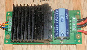 I
eventually changed the Vortex controllers out for smaller
Devantech MD03 H-Bridge controllers which implement their direction
reversals using solid-state switching and are much "quieter"
audibly and electrically. The latter makes life much easier for the chips.
Important also is that change of direction can be
accomplished without any delay arising from the
controller mechanical operation and this results
in much smoother movement at the cockpit. The experiment
with the Vortex units was very useful however as it also
gave me a much better feel for how much work the speed
controllers actually had to do - not as much as I'd first
thought. The MD03 controllers are only 20 Amp units and only
the one driving the paired Heave DOF drive motors shows any
sign of warming-up in operation.
I
eventually changed the Vortex controllers out for smaller
Devantech MD03 H-Bridge controllers which implement their direction
reversals using solid-state switching and are much "quieter"
audibly and electrically. The latter makes life much easier for the chips.
Important also is that change of direction can be
accomplished without any delay arising from the
controller mechanical operation and this results
in much smoother movement at the cockpit. The experiment
with the Vortex units was very useful however as it also
gave me a much better feel for how much work the speed
controllers actually had to do - not as much as I'd first
thought. The MD03 controllers are only 20 Amp units and only
the one driving the paired Heave DOF drive motors shows any
sign of warming-up in operation.
The MD03 units will accept a
range of control signals including the capability to follow
a 0 to 5V PWM speed demand signal and this is how they are
driven by the Signal Processor Unit. They seem effective at
holding the cockpit at any demanded position even when the
cockpit load is unbalanced - eg they are quite happy driving
the heave motion when the seat is unoccupied and there is a
significant unbalanced torque acting on the heave motors.
Putting the control system
together (The SPU design has now
been updated - click here)
Below is a wiring diagram for
the overall system. This can be read in conjunction with the
wiring diagrams for the Signal Processor Units to understand
how the electrical system is put together. Click on the
image for a bigger printable version.
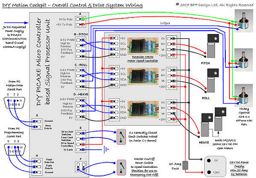
The Signal Processor Unit is
connected to the PC via two serial connections - one for the
chip programming and the other to receive the motion data. I
have both of these connected at once to different COM ports
to allow me to make changes to the PICAXE chip programming
when I need to. However if you weren't interested in
changing the chip programming the same COM port could be used for both
tasks - the
"Motion Data" connection could be made after the chips had
been flashed. You will have to cut up a couple of serial
cables to get the free wires to connect to the board - or
fit serial connectors directly.
The high current cabling for the electric motor
drive end is made with 2.5mm^2 35Amp cable which is
considerably thicker than the 1/0.6 mm single core equipment
wire recommended by PICAXE for the bread-board wiring.
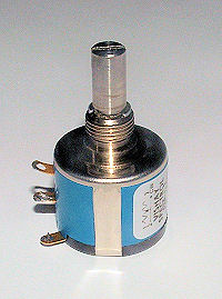 The
multi-turn position feedback potentiometers are mounted on
their respective motor output shafts so that they signal the
actual position of the cockpit movement. It is very important that
they are wired so that the direction of increasing voltage output from the
pot matches the +ve direction of movement of the motor -
otherwise the position feedback loop will be unstable and
the cockpit will constantly drive into its end stops.
The
multi-turn position feedback potentiometers are mounted on
their respective motor output shafts so that they signal the
actual position of the cockpit movement. It is very important that
they are wired so that the direction of increasing voltage output from the
pot matches the +ve direction of movement of the motor -
otherwise the position feedback loop will be unstable and
the cockpit will constantly drive into its end stops.
The end-of-travel limit
switches should be positioned so that they are triggered and
held open as a DOF approaches its end of travel - best in
fact to set them some distance short of the actual physical end-of-travel
to allow some stopping distance for the drive. Often when
things go wrong (just when they are needed) the system will end up
driving towards the end stops with considerable speed and
some distance will be needed to decelerate the motion after
the power is cut. The
5V logic power supply to the MD03 motor controllers is wired
through the limit switches and the master on/off switch in
series - so any limit switch moving into an OPEN position
will cut the drive to all the motors. It is a good idea to
position the master on/off switch where it can be used as an
emergency cut-off switch by either the cockpit occupant or
an on-looker. Additional switches can be added in series as
needed.
A 9V DC regulated power
supply will be needed for the PICAXE Experimenter board, I
have used a 1200mA supply which doesn't seem to have any
difficulties with current capacity. The 5V supplies to the potentiometers and MD03
controllers are all taken from the Experimenter board. I am
currently using two very old 12V 38AmpH Lead-Acid deep cycle
batteries from previous electric vehicle projects to power
the drive motors but a mains powered 24V DC power supply
with a capacity of about 25 Amps might do - check the MD03
documentation or manufacturer for compatibility.
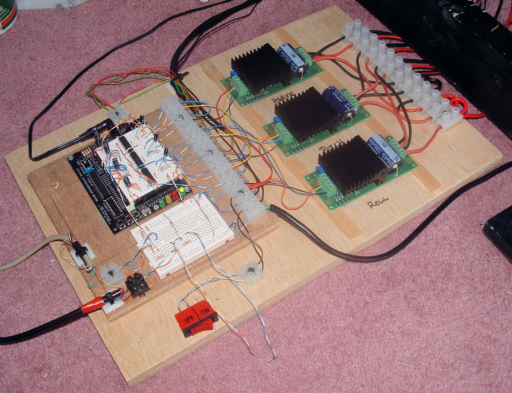
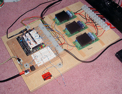 The main elements of the
system are mounted on plywood and secured to ensure they
don't move about, as are the cables which are secured with
cable ties. The breadboard cabling is susceptible to
loosening if other cables etc are dragged over it (eg as the
motion cockpit moves) so make sure the Signal Processor Unit
is protected with a cover. Try to keep the LEDs on the
Experimenter board visible though - they flash each time a
new position demand is processed and give a very useful visual
indication that the system is running and how fast it is
processing data.
The main elements of the
system are mounted on plywood and secured to ensure they
don't move about, as are the cables which are secured with
cable ties. The breadboard cabling is susceptible to
loosening if other cables etc are dragged over it (eg as the
motion cockpit moves) so make sure the Signal Processor Unit
is protected with a cover. Try to keep the LEDs on the
Experimenter board visible though - they flash each time a
new position demand is processed and give a very useful visual
indication that the system is running and how fast it is
processing data.
So, that's the drive system.
If you were interested in building a motion cockpit a good
place to start, and one which won't break the bank
instantly, might be to firstly build and get running the
Signal Processor Unit and then later tie it to speed
controllers and drive motors. The Motion Drive software and PICAXE chip programming are
avaiable
from this site, and the PICAXE Experimenter
kit and chips are fairly inexpensive. Note also that you
don't have to use all the outputs - you could use just the
Pitch and Roll DOF drives for a 2 rather than 3 DOF
system......
Question! How can
the system be modified to provide a 6-DOF drive? I think
probably quite straightforwardly - but that's a project for another day!
© This site is
copyrighted, If you'd like more information or have any
comments please contact me at