NOTE This SPU has now
been substantially simplified to run with new PID Servo
Controller software - see here for
more details.
The OLD Signal Processor Unit is built around four programmable micro-controller
chips to process the digital cockpit position demand
data coming from the PC and to output matching speed demand
signals for the movement cockpit's motor speed controllers.
These micro-controller chips are amazing wee things, they only cost a few pounds
each and can be programmed to do all sorts of things. I have
used
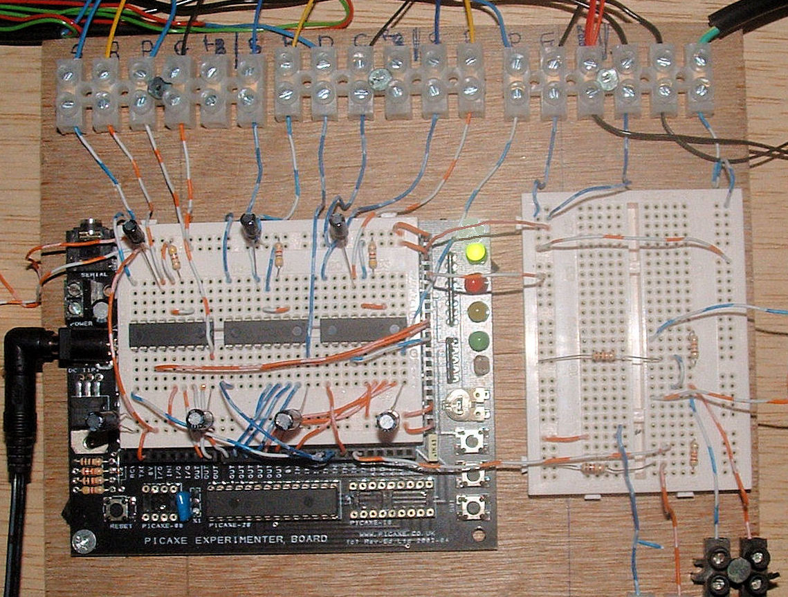
PICAXE chips – one 28X
and three 18X, and have built up the unit around the
PICAXE
Experimenter Kit which provides a bread-boarding area for
your own component placement and solderless connections as
well as power supply connections, LEDs etc. (Check
here for
your local distributor of PICAXE chips.)
The
single 28X chip is the main data receiving chip and is located in the
connector provided on the Experimenter board. It reads the serial output
sent from the PC as
often as the PC can send it. It then splits the received data packet
into data for each DOF, tells the individual 18X chips that
new position data is ready and then, once it has their attention, sends the
position demand data on to the 18X chips.
The 18X chips are mounted on the white bread-boarding area
and each runs
one of the movement cockpit's DOF's. Each takes a position
demand from the 28X, reads the current DOF position from a
multi-turn potentiometer on its drive motor and determines
in what direction and how fast it needs to run the drive
motor to take the DOF to the new demanded position.
Each 18X
chips runs independently, continually monitoring the actual
position of the cockpit and adjusting its motor speed to
suit. Each will accept a new position demand from the PC
whenever one is available but without significantly
interrupting its control of the cockpit. This means that any loss
of signal from the PC simply results in the cockpit driving
to the last demanded position and stopping there.
28X, reads the current DOF position from a
multi-turn potentiometer on its drive motor and determines
in what direction and how fast it needs to run the drive
motor to take the DOF to the new demanded position.
Each 18X
chips runs independently, continually monitoring the actual
position of the cockpit and adjusting its motor speed to
suit. Each will accept a new position demand from the PC
whenever one is available but without significantly
interrupting its control of the cockpit. This means that any loss
of signal from the PC simply results in the cockpit driving
to the last demanded position and stopping there.
The calculation cycle in the
18X takes about 40ms, so each DOF has it's position
monitored and adjusted if necessary about 25 times per
second. The speed at which new position demand signals come
from the 28X however depends on how fast the Motion Driver
software running on the PC is exporting the data - and this
depends mainly on how fast it can be extracted from the FS9
simulation. With the current software version which uses
FSUIPC for all its data calls this is about once every
40ms also. The 18X chips only interrupt their position
monitoring/adjustment cycle when the 28X signals that new
data is ready - so not every monitoring loop involves a new
position demand input. For full details of how this is done
you can download the Flash programs for the chips from below
or from the downloads page - they are
written in a flavour of Basic and are fairly easy to read.
 The main output from the
Signal Processor Unit to the motor speed
controllers is in the form of a 0 to 5V variable PWM voltage
(at 20kHz) which indicates required motor speed and a high/low 5V
signal to indicate forward or reverse drive. These are
compatible with the
Devantech MD03 H-Bridge motor
speed controllers used.
The main output from the
Signal Processor Unit to the motor speed
controllers is in the form of a 0 to 5V variable PWM voltage
(at 20kHz) which indicates required motor speed and a high/low 5V
signal to indicate forward or reverse drive. These are
compatible with the
Devantech MD03 H-Bridge motor
speed controllers used.
The Signal Processor has a few safety features built-in – for example
the 18X chip stops driving if the position feedback
potentiometer approaches its end of travel or produces an
end-of-scale reading, and the 28X chip shuts down if there
is a time-out on the data transfer hand-shaking with the 18X
chips. Note also that the cockpit is fitted with
end-of-travel limit switches which cut the logic supply
voltage to the MD03 motor controllers and so cut the drive
to the motors if any of the limit switches are triggered.
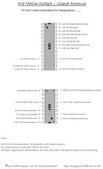
The PICAXE
micro-controller pin designations can be seen
here and
this can be read in conjunction with the flash programming
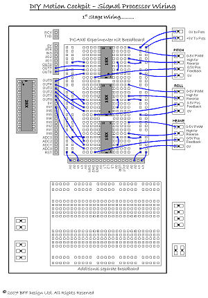
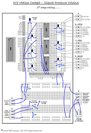
below to understand what's going on. The unit wiring is a
wee bit complicated and I've made up two wiring diagrams
which show the wiring tackled in two stages - the first
covers most of the core wiring on the Experimenter board and the
second shows the rest plus that on the second bread-boarding
area.
The Experimenter Kit comes
with a data sheet which shows how (after a bit of thought)
the base circuit board is put together - I think you can
also buy it pre-assembled. Once this is done
you can mount it and the second breadboard on a piece of
plywood and get on with the custom wiring. PICAXE
recommend that the low current logic type wiring on the
breadboards and chips is made with 1/0.6 mm single core
equipment wire. I used single 0.5 mm strand wire from
telephone cable with a small bend made in the stripped ends
to ensure a firm contact in the breadboard.
The capacitors in the system
are there as a protection from any voltage spikes in the pot
or reverse signal lines and are mainly a hangover from the
experiments with the 4QD Vortex speed controllers. I've left
them in as they don't seem to do any harm and will still
offer some protection. The resistors are as specified in the
standard PICAXE chip interfacing circuits and are necessary
so don't leave them out.
PICAXE Programming
The chip programming is in
Basic and is downloaded to the chips using the
PICAXE
programming software which is available free from their web
site. The local programming connections to the chips on the
board can be made using the "Read" and "Write" jump wires
which carry the signals from Connector H in the wiring
diagrams. Connect these to
the In and Out Serial programming pins on the chip you want
to flash. This can also be done by removing the chip from
the bread-boarding area and
installing it in the provided connector on the Experimenter
board, but this can be very disruptive once all the wing has
been made. Remember that the Serial-In pin must be tied low
when it is not connected to the programming circuit.
The original chip programs
were as
follows -
ReadPos.bas - the 28X flash
program - Read position data from PC COM
port & distribute.
Pos2SpeedPitch.bas - Pitch
DOF 18X program - Pitch motor
controller speed demand.
Pos2SpeedRoll.bas - Roll DOF
18X program - Roll motor
controller speed demand.
Pos2SpeedHeave.bas - Heave
DOF 18X program - Heave motor
controller speed demand.
The three 18X programs are
the same with the exception of some variation in variables
affecting speed and smoothness of response. The files can be opened using NotePad but are best
viewed with the free PICAXE programming software (they are
nicely colour formatted). I've
commented them fairly extensively so their function should
be understandable. They are available from the
downloads
page here.
As of October 07 there
are updated v2.0 chip programs available. These now have the
facility to be configured directly from the Driver Setup
program running on the PC - ie the key settings which define
the SPU performance for each DOF can be set from the PC
without the need to re-flash the chips. This greatly assists
the rig set up process and also simplifies the chip
programming process - each need only be flashed once and the
same program is used for all the 18X chips. The v2.0
programs are -
ReadPosGeneric.bas - the 28X flash
program - Read position data from PC COM
port & distribute + 18X initialisation and EEPROM
storage of settings.
Pos2SpeedGeneric.bas - A
single program to program all the 18X chips - motor
controller speed demand.
Both are available from the
downloads
page here.