The flight sim motion cockpit drive software and
control system was always going to be the biggest challenge
for me. Proprietary motion cue software for flight
simulators is probably available to buy. However the experience of other DIY
motion
platform builders encourages the view that at least having a
go at developing the drive software and control elements myself makes sense
as it would substantially reduce the cost of the overall
system. So
I've had a go at it.....
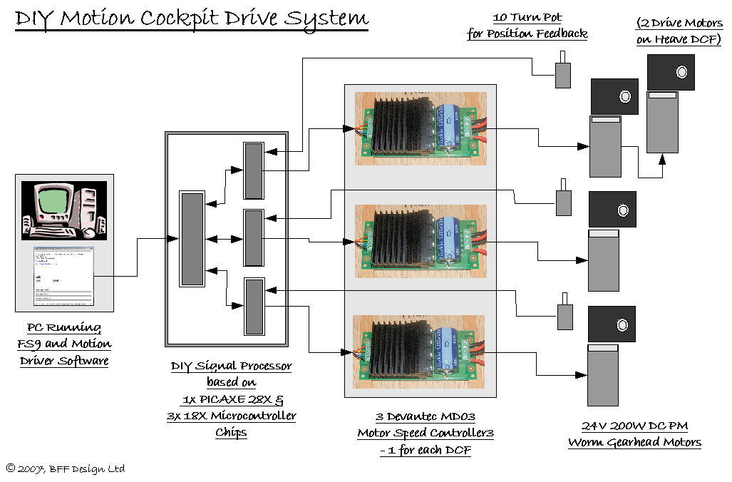
So what's in the DIY system?
(Schematic above - click for bigger image) -
System Now Updated - See HERE
-
At its front end is FS9
and my Motion Drive
software application running on the same PC.
The Motion Drive software is written in the
AutoHotKey (AHK)
scripting language and, with the aid of other free
utilities, pulls the detailed
aircraft flight motion parameters from FS2004, does the
math to determine the appropriate movement cues and sends them
down a serial port connection to a micro-controller
based Signal Processor unit. The cues are output
from the PC in the form of digital
position demand signals for each movement DOF.
-
There is a DIY
micro-controller based Signal Processor unit which
receives the digital position demands sent from the PC.
It also receives actual cockpit position feedback data from
multi-turn potentiometers on the moving
cockpit and using these two sets of data continuously
converts the digital position demand data from the
PC into analogue speed demand voltages needed
to control the drive
motors. These are output as three 0 to 5 Volt pulse
width modulated (PWM) variable voltage signals which
can be read directly by the high current motor speed controllers
to drive the motors for each DOF. The Signal Processor
unit is in effect a digital position to analogue speed
demand converter.
-
There are three proprietary
H-Bridge motor speed controllers which do the hard electrical
work of driving the electric motors. These control the speed
and direction of the motors as directed by the
Signal Processor units and handle the full drive currents
of the motors.
-
And finally there are
multi-turn potentiometers mounted on each drive motor
which provide feedback to the Signal Processor Unit,
this
tells it where each DOF actually is at any moment in
time - these are essential because they allow the
control system to decide in what direction and how fast
to run each motor to get the cockpit to move where the
Motion Drive software wants it.
There are other elements to
the system too, such as a 9V regulated power supply to power
the electronics and a 24V DC supply to power the motors but
those listed above are the main working elements.
The drive system has evolved
through a few variations in which I've changed or adjusted
all the main elements including the software, micro-controller
programming and the type of speed controllers used. It now performs
well considering it is a DIY build with very little delay between the
flight motions occurring in FS9 and the cockpit moving in
response. The Motion Drive software has been
structured to allow the programming of the motion cues to be
altered and updated - the motion cue programming
for each DOF is in the form of a separate AHK script. If you
know what you are doing this scripting can be customised in
the OpenSource version to
give the cues you are looking for if my programming attempts
don't suit you.
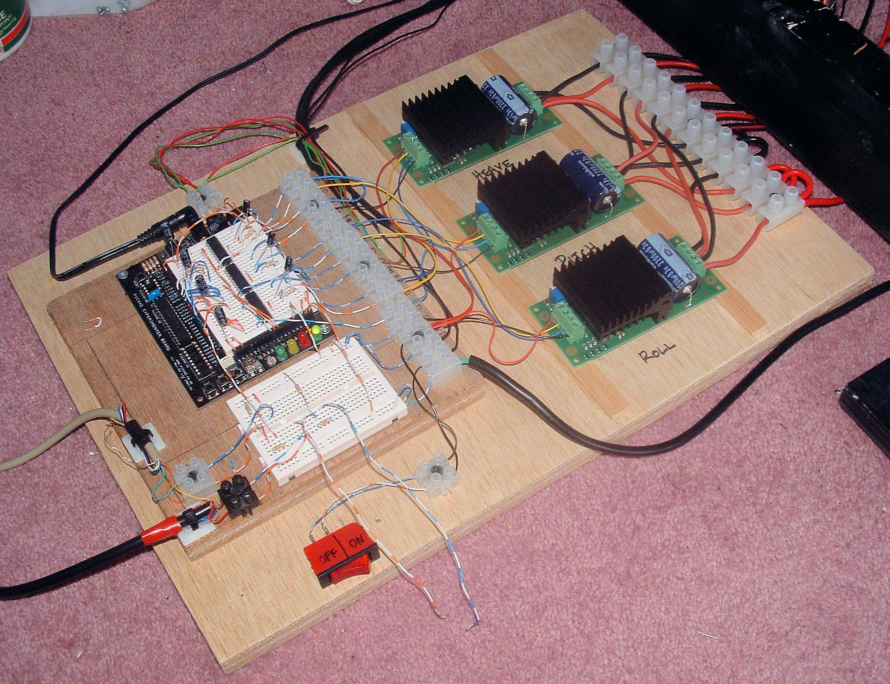
 The
drive system has been relatively easy to build as it uses readily
available components and easy to work with bread-boarding
methods, electrical connections and wring. The high current
side is a 24V DC system so there are no direct mains
electricity connections and as such it represents a much
reduced electrical hazard.
The
drive system has been relatively easy to build as it uses readily
available components and easy to work with bread-boarding
methods, electrical connections and wring. The high current
side is a 24V DC system so there are no direct mains
electricity connections and as such it represents a much
reduced electrical hazard.
I've now managed to get the
drive system running fairly well. Changes to the motor speed
controllers have resulted in an electrically "quieter"
system in which the micro-controllers are stable and run
fairly reliably. Changes to the way in which data is read
from FS9 have resulted in a much faster data transfer rate
with new position demand signals now being sent to the drive
system every 60ms - about 18 sets per second. And changes to
the motion cue programming have given better cues and a
better set of programming tools for further development. It
is still a low cost DIY system however and will not be as
robust as paid-for commercial drives. In particular its high
frequency response is limited and demanded oscillations of
frequency much above 1 Hz start to be lost - room for
development!
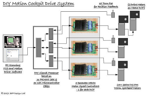
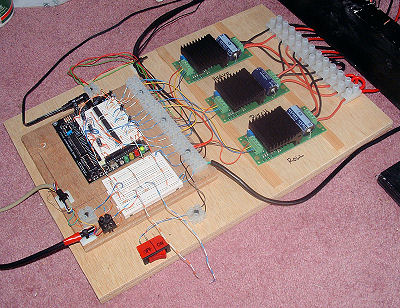
Original SPU Design Original Overall Wiring
© This site is
copyrighted, If you'd like more information or have any
comments please contact me at